Apparatus for differentiating blood cells using back-scatter

a back-scattering and blood cell technology, applied in chemical methods analysis, instruments, phase/state change investigation, etc., can solve the problems of platelet agitation, time-consuming and costly tagging step, and somewhat inaccurate cell count of cell type of interes

Inactive Publication Date: 2005-03-22
COULTER INTERNATIONAL CORPORATION
View PDF18 Cites 52 Cited by
  • Summary
  • Abstract
  • Description
  • Claims
  • Application Information

AI Technical Summary

Benefits of technology

Thus, a preferred method for differentiating blood cells in a blood sample containing both platelets and non-platelet particles comprises the steps of (a) passing the individual particles of the blood sample, one at a time, through a cell-interrogation zone in which each cell is irradiated by a beam of radiation; (b) simultaneously (i) detecting the level of back-scattered radiation from each irradiated particle through a plurality of optical fibers positioned to optically couple the back-scattered radiation to a high-gain photodetector, and (ii) detecting the level of another measurable effect produced by the particle passing through the cell-interrogation zone; (c) producing first and second signals proportional to the respective levels of the detected back-scattered radiation and the other measurable effect; and (d) using the first and second signals to differentiate blood cells of interest from other cells and particles in the blood sample. As indicated above, the other measurable effect of the irradiated particle includes the level of forwardly scattered light within a certain angular range, the level of side-scattered light, the amount of light loss in the irradiating beam caused by the presence of the irradiated particle in the beam, or a change in level of either a DC or an RF current passing through the interrogation zone occasioned by the passage of a cell through such zone.
According to another aspect of the invention, apparatus for differentiating

Problems solved by technology

Unfortunately, this ideal is sometimes difficult to realize since, for many reasons, a small percentage of cells of one type invariably invade the spatial domain of cells of other types, thereby making the cell count of a cell type of interest somewhat imprecise.
This tagging step, of course, is both time-consuming and costly.
Further, this tagging of platelets subjects the platelets to considerable agitation or manipulation, which has an undesired effect on platelet activation.
As indicated above, however, all of these schemes are susceptible to cross-contamination by non-platelets, introducing a certain degree of uncertainty in the data reported.
The impedance approach is problematic in that any cell debris having a volume similar to that of a normal platelet will be displayed and counted as a platelet.
The forward scatter approach is problematic in that cellular debris of the same size or volume as a platelet will produce a forward-scatter signature similar to a platelet and thereby be counted as a platelet.
Unfortunately, such large detectors are problematic in that they also collect stray light reflected by various surfaces within the optical system and thereby produce signals having a relatively low signal-to-noise ratio.
Even when shaped to exclude the collection of stray light (e.g., shaped as a circular ring centered about the irradiating beam axis), these photodetectors still require a substantial surface area to achieve the gain necessary to sense the scattered radiation, and the larger the surface area, the slower the electrical response time.
Schemes that combine the electrica

Method used


Image

  • Apparatus for differentiating blood cells using back-scatter
  • Apparatus for differentiating blood cells using back-scatter
  • Apparatus for differentiating blood cells using back-scatter

Examples


Embodiment Construction

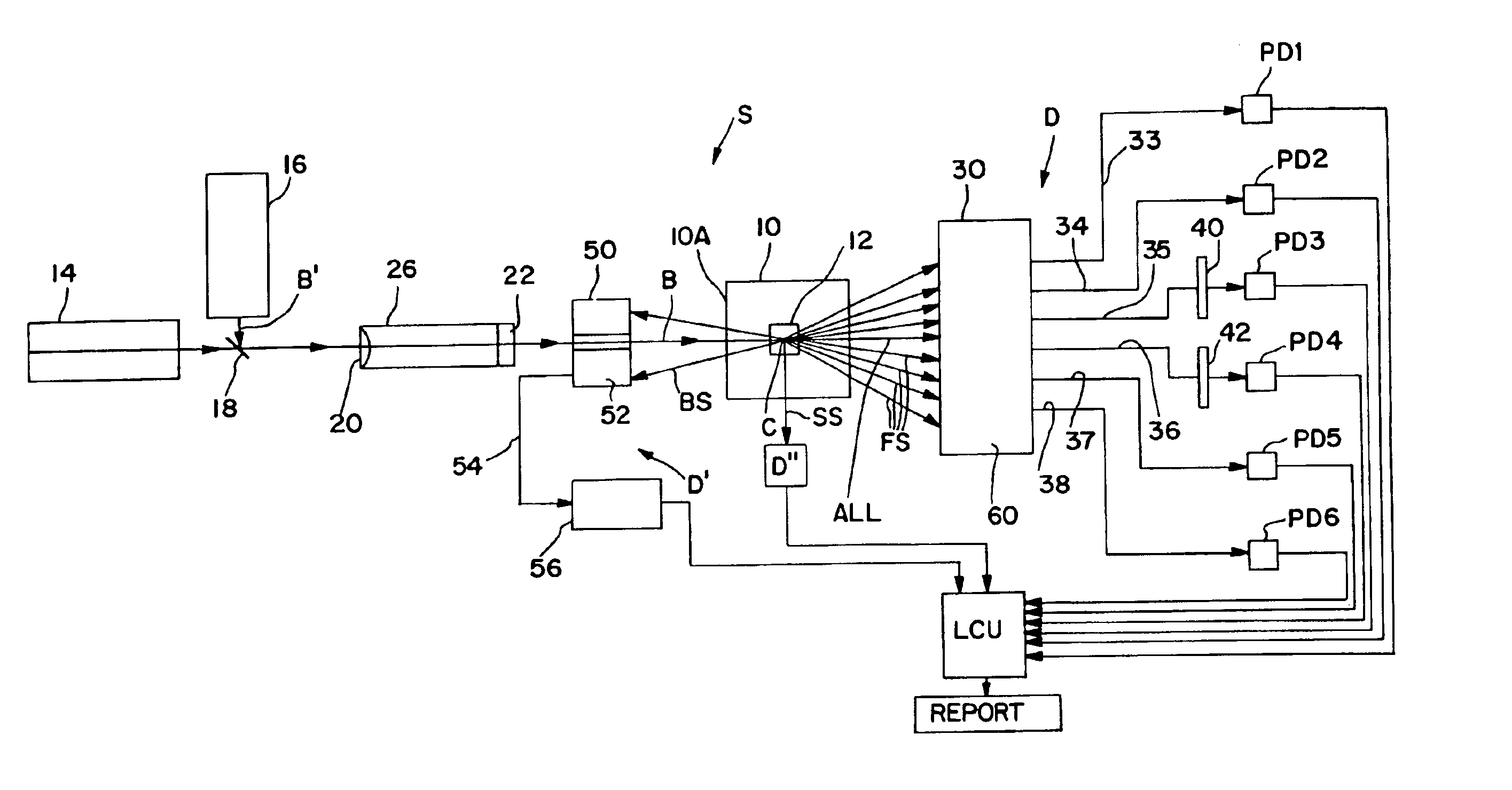
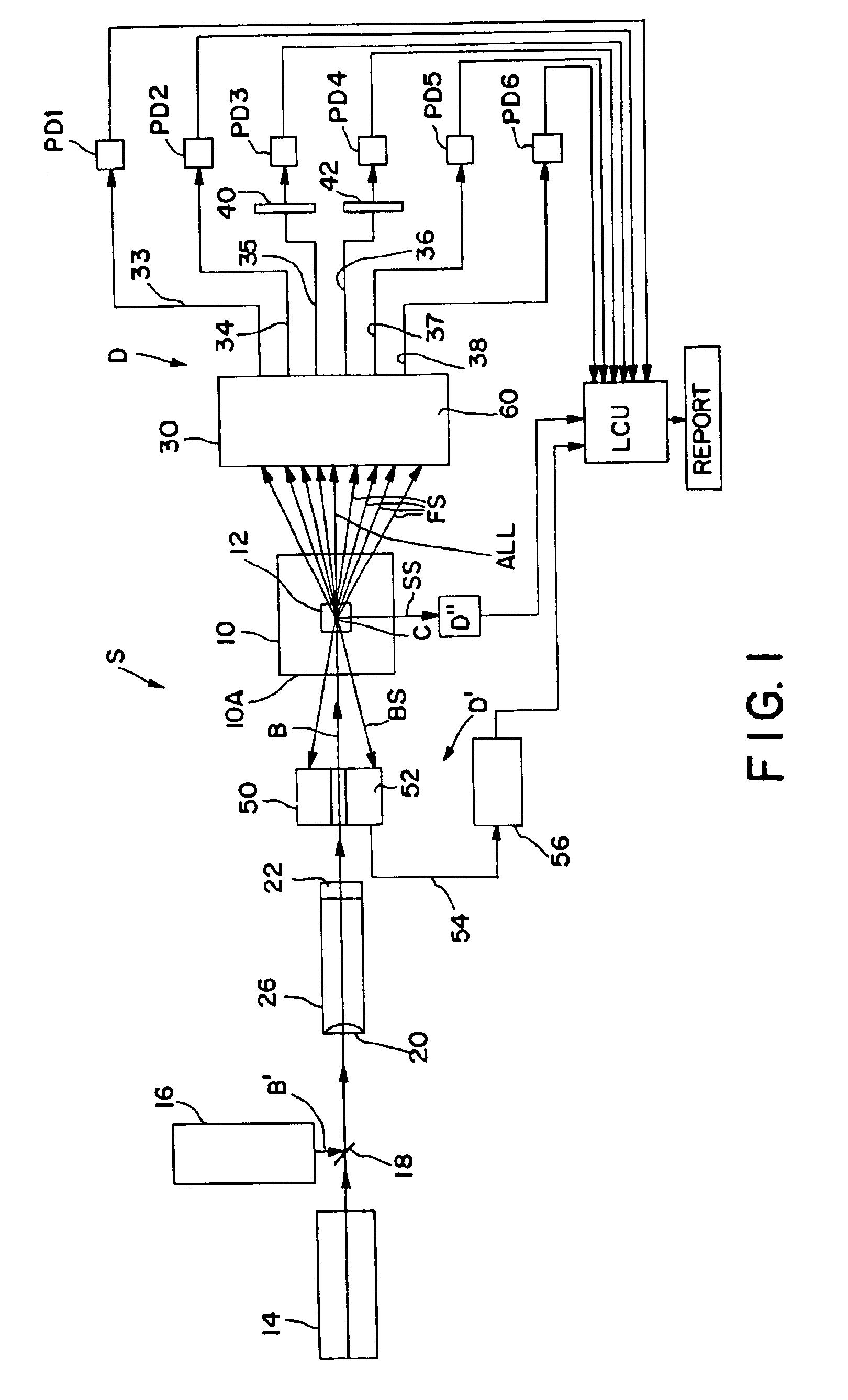
Referring now to the drawings, FIG. 1 schematically illustrates an electrooptical system S adapted to carry out the blood cell-differentiating method of the invention. System S is designed to be retro-fitted into a standard XL™ Flow Cytometer made and sold by Beckman Coulter, Inc. System S comprises a forward scatter / axial light-loss detector D, a back-scatter detector D′ and a side-scatter detector D″. The respective electrical output signals produced by these detectors are fed to and processed by a suitably programmed microprocessor of a Logic and Control Unit (LCU) comprising the flow cytometer instrument. Based on the instrument's programming, various particle parameters detected by detectors D, D′ and D″ are reported and displayed, e.g., as histograms and scattergrams, as presented below.

Central to system S is an optical flow cell 10 having a centrally located particle-interrogation zone 12 through which a stream of individual particles in suspension can be made to pass, one at...


PUM


Abstract

Blood cells of interest are readily distinguishable from other blood cells and look-a-like particles found in a blood sample by their back-scatter signature. A preferred method for differentiating platelets in a blood sample is to irradiate the cells and particles, one at a time, with a beam of radiation, and to detect back-scattered (reflected) radiation using a plurality of optical fibers to transmit the back-scattered radiation to a high-gain photodetector, e.g. a photomultiplier tube. Preferably, the back-scatter signal so obtained is combined with a second signal representing, for example, either the level of forward-scatter within a prescribed, relatively narrow angular range, or the level of side-scattered radiation, or the level of attenuation of the cell-irradiating beam caused by the presence of the irradiated cell or particle in the beam, or the electrical impedance of the irradiated cell or particle, to differentiate the cells of interest. The method and apparatus of the invention are particularly useful in differentiating platelets and basophils in a blood sample.

Description

FIELD OF THE INVENTIONThe present invention relates to methods and apparatus for differentiating various types of blood cells on the basis of their respective light-scatter signature. More particularly, it relates to a method and apparatus for differentiating blood cells, and especially platelets and basophils, on the basis of their back-scatter signature.BACKGROUND OF THE INVENTIONThe use of light scattering measurements as a means for differentiating various types of small particles is well known. For example, in virtually all sophisticated hematology instruments, it is common to measure the forward light scattering properties of blood cells by passing the cells, one at a time, through the interrogation zone of an optical flow cell. While in the interrogation zone, each cell is irradiated by a laser beam, and one or more photodetectors, strategically positioned forward of the interrogation zone, operate to sense the level of forward scattered radiation, often within several differ...

Claims


Application Information

Patent Timeline
IPC IPC(8): G01N15/10G01N15/14G01N33/49G01N15/00
CPCG01N15/1031G01N15/1459G01N2015/008G01N2015/0084Y10T436/101666G01N2015/1486G01N2015/1493Y10T436/10G01N2015/1006
Inventor KRAMER, DONALD L.
Owner COULTER INTERNATIONAL CORPORATION
Why Eureka
Try Eureka