The
advantage of the present invention is obtaining a
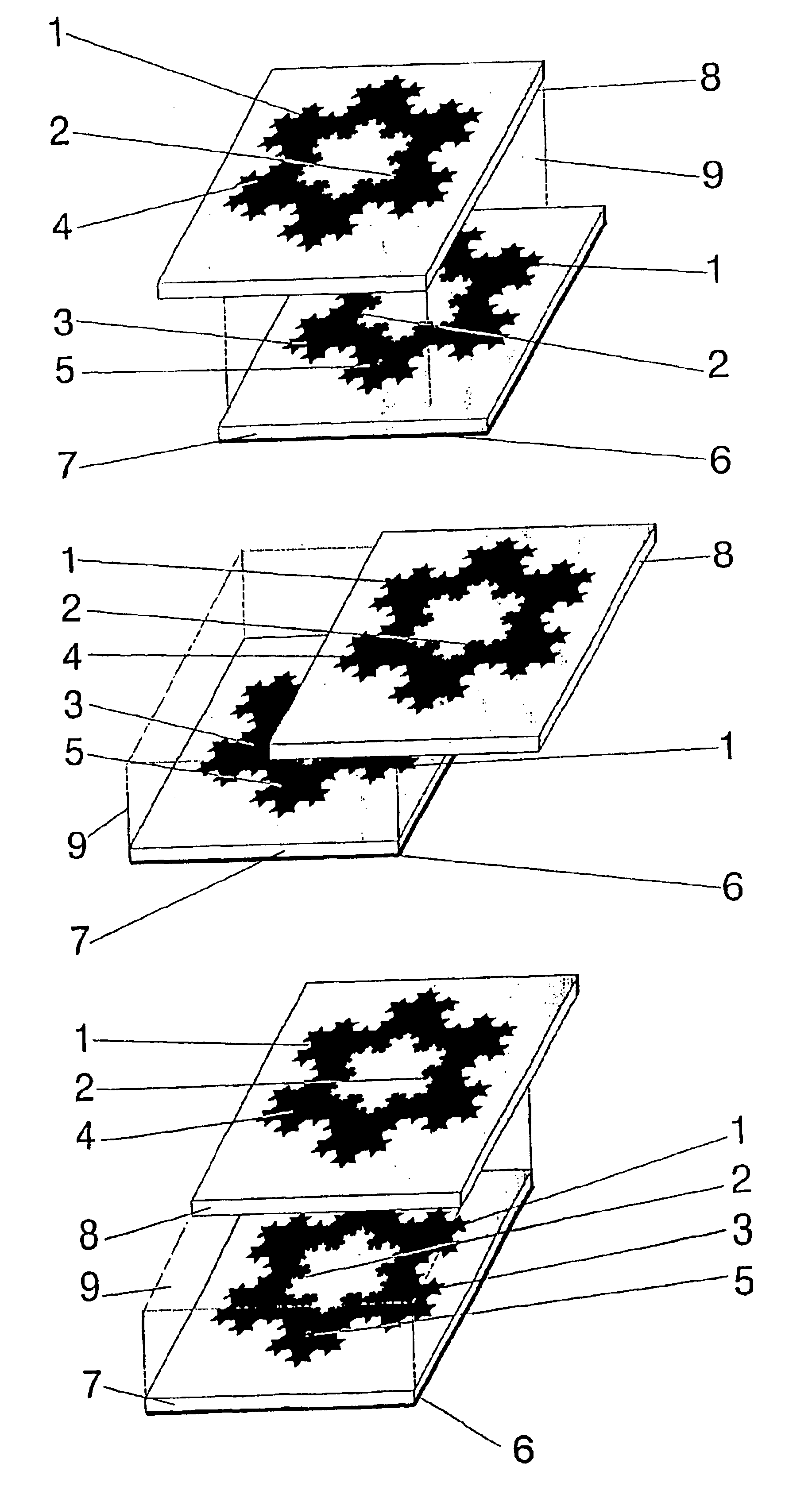
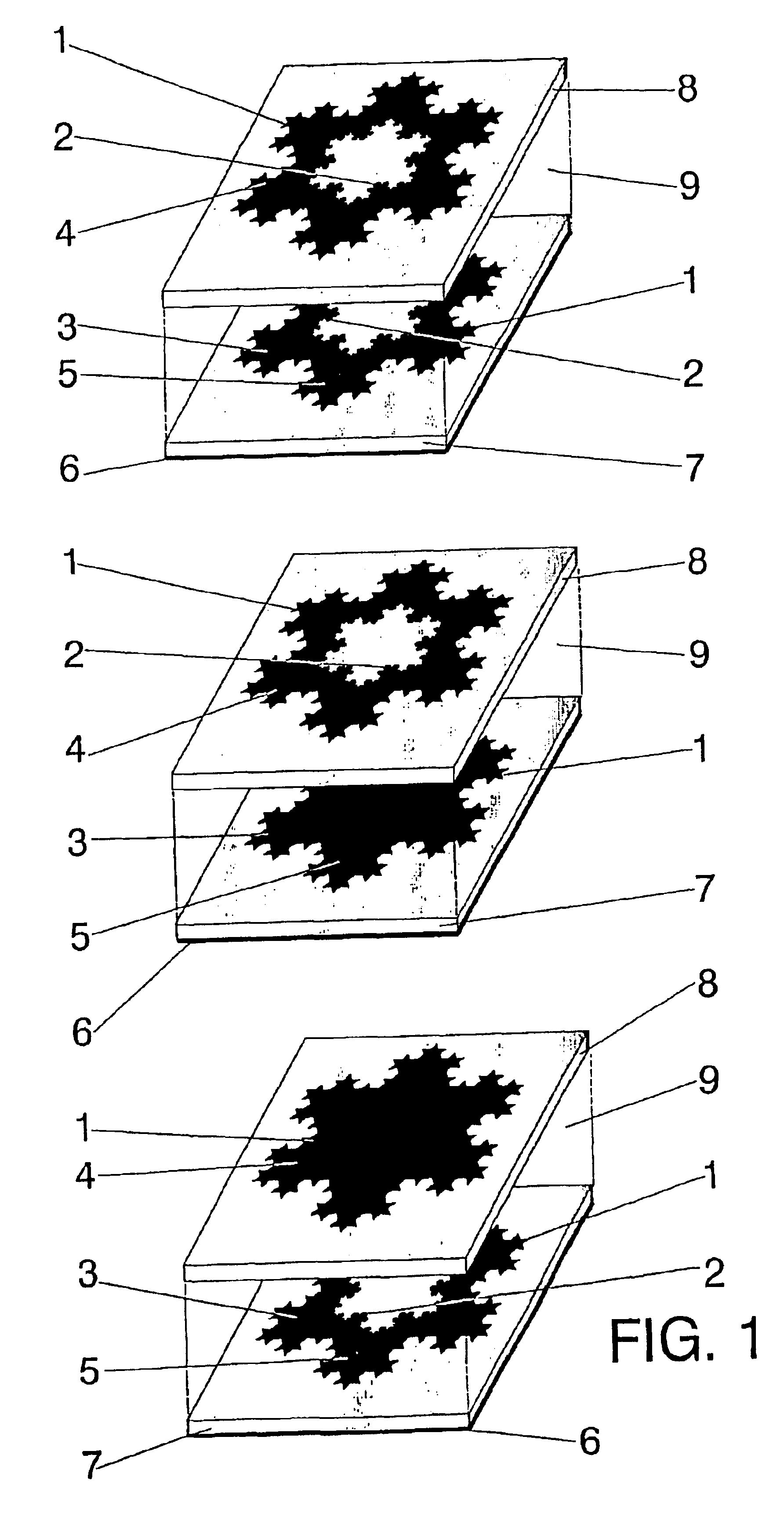
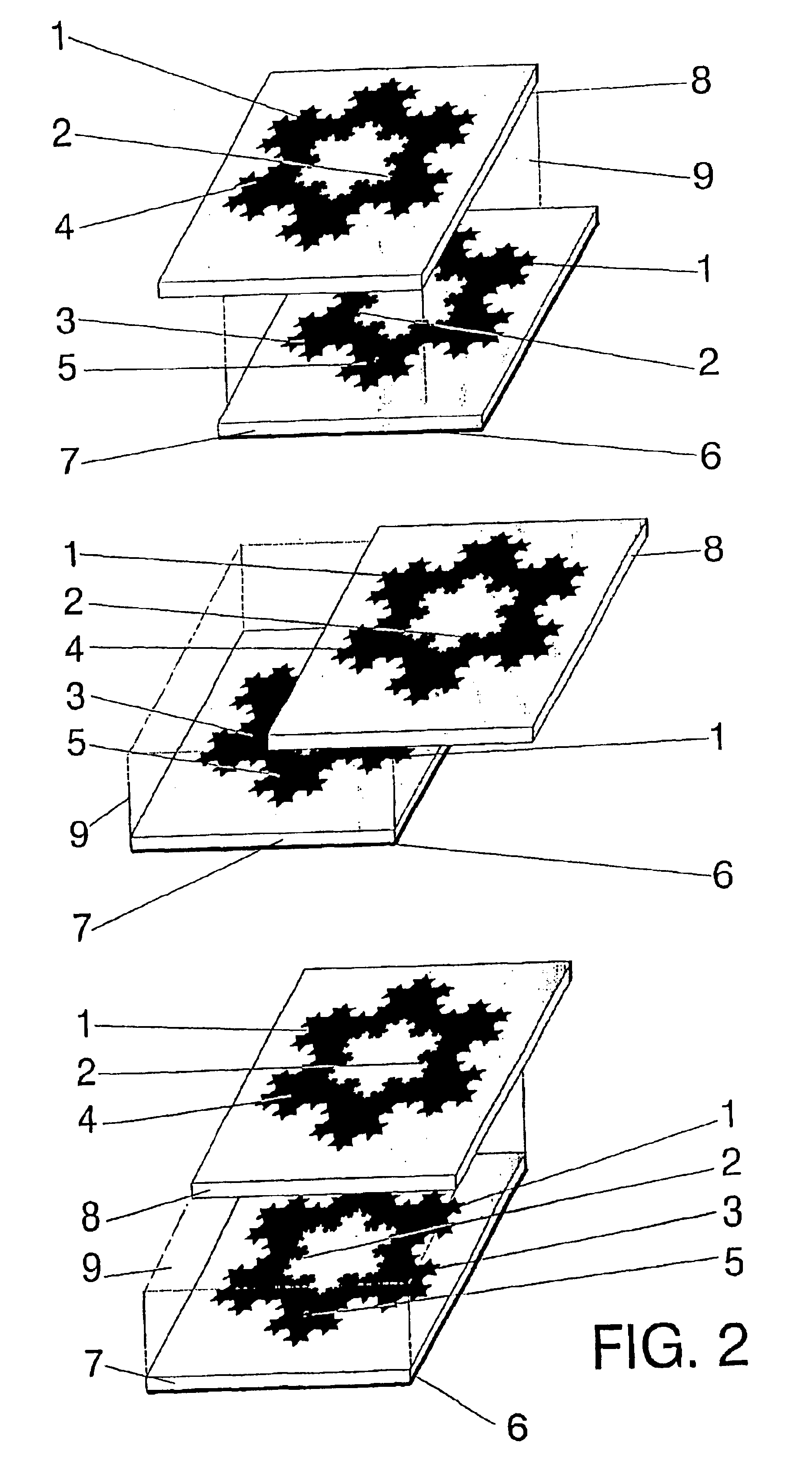
microstrip patch antenna of a
reduced size when compared to the classical patch antennas, yet performing with a large bandwidth. The proposed antenna is based on a stacked patch configuration composed by a first conducting surface (the active patch) substantially parallel to a conducting ground counterpoise or ground-plane, and a second conducting surface (the parasitic patch) placed parallel over such active patch. Such parasitic patch is placed above the active patch so the active patch is placed between said parasitic patch an said ground-plane. One or more feeding sources can be used to excite the said active patch. The feeding element of said active patch can be any of the well known feeding element described in the prior art (such as for instance a
coaxial probe, a co-planar microstrip line, a
capacitive coupling or an aperture at the ground-plane) for other microstrip patch antennas.
is obtaining a
microstrip patch antenna of a
reduced size when compared to the classical patch antennas, yet performing with a large bandwidth. The proposed antenna is based on a stacked patch configuration composed by a first conducting surface (the active patch) substantially parallel to a conducting ground counterpoise or ground-plane, and a second conducting surface (the parasitic patch) placed parallel over such active patch. Such parasitic patch is placed above the active patch so the active patch is placed between said parasitic patch an said ground-plane. One or more feeding sources can be used to excite the said active patch. The feeding element of said active patch can be any of the well known feeding element described in the prior art (such as for instance a
coaxial probe, a co-planar microstrip line, a
capacitive coupling or an aperture at the ground-plane) for other microstrip patch antennas.
The essential part of the invention is the particular geometry of either the active or the parasitic patches (or both). Said geometry (RSFS) consists on a ring, with an outer perimeter enclosing the patch and an inner perimeter defining a region within the patch with no conducting material. The characteristic feature of the invention is the shape of either the inner our outer perimeter of the ring, either on the active or parasitic patches (or in both of them). Said characteristic perimeter is shaped as an space-filing curve (SFC), i.e., a curve that is large in terms of physical length but small in terms of the area in which the curve can be included. More precisely, the following definition is taken in this document for a space-filling curve: a curve composed by at least ten segments which are connected in such a way that each segment forms an angle with their neighbours, i.e., no pair of adjacent segments define a larger
straight segment, and wherein the curve can be optionally periodic along a fixed straight direction of space if and only if the period is defined by a non-periodic curve composed by at least ten connected segments and no pair of said adjacent and connected segments define a straight longer segment. Also, whatever the design of such SFC is, it never intersects with itself at any point except the initial and final points (that is, the whole curve is arranged as a
closed loop definning either the inner or outer perimeter of one patch within the antenna conifiguration). Due to the angles between segments, the physical length of said space-filling curve is always larger than that of any straight line that can be fitted in the same area (surface) as said space-filling curve. Additionally, to properly shape the structure of the miniature
patch antenna according to the present invention, the segments of the SFC curves must be shorter than a tenth of the free-space operating wavelength.
The function of the parasitic patch is to enhance the bandwidth of the whole antenna set. Depending on the thickness and size constrain and the particular application, a further
size reduction is achieved by using the same essential configuration for the parasitic patch placed on top of the active patch.
It is precisely due to the particular SFC shape of the inner or outer (or both) perimeters of the ring on either the active or parasitic patches that the antenna features a low resonant frequency, and therefore the antenna size can be reduced compared to a conventional antenna. Due to such a particular geometry of the ring shape, the invention is named
Microstrip Space-Filling Ring antenna (also MSFR antenna). Also, even in a
solid patch configuration with no central hole for the ring, shaping the patch perimeter as an SFC contributes to reduce the antenna size (although the
size reduction is in this case not as significant as in the ring case).
The
advantage of using the MSFR configuration disclosed in the present document (FIG. 1) is threefold:(a) Given a particular
operating frequency or wavelength, said MSFR antenna has a reduced electrical size with respect to prior art.(b) Given the physical size of the MSFR antenna, said antenna can operate at a lower frequency (a longer wavelength) than prior art.(c) Given a particular
operating frequency or wavelength, said MSFR antenna has a larger
impedance bandwidth with respect to prior art.

