Illumination device and method for laser projector

a laser projector and projection device technology, applied in the field of projection displays, can solve the problems of maximizing brightness, truncated light is obviously wasted, and achieves the effects of reducing beam sampling rate, reducing cost, and improving light efficiency

Inactive Publication Date: 2005-03-22
FLIR SYSTEMS TRADING BELGIUM BVBA
View PDF4 Cites 50 Cited by
  • Summary
  • Abstract
  • Description
  • Claims
  • Application Information

AI Technical Summary

Benefits of technology

One or more of the problems outlined above may be solved by the various embodiments of the invention. The present invention performs a similar function as a lenslet array optical system, but does so more effectively, with fewer and lower cost components, and with improved design flexibility. The present techniques may be applied to many types of illumination sources such as arc lamps and LED's in addition to lasers.
Broadly speaking, the invention comprises a system and method for converting a laser beam having a non-uniform profile into a source of illumination which has uniform power density. The generated illumination image may be used for a variety of purposes. For example, the image may be a uniformly intense rectangle suitable for use in a display device, or it may be a round dot suitable for transmitting the light into an optical fiber. The present invention can be used to conserve the power generated by the laser source and direct substantially all of the power into the desired illumination region. Laser speckle artifacts can also be reduced or eliminated at the same time. The choice of design of the elements in the system allows for precise control of the illumination pattern and the particular telecentric cone angle patterns exiting the illumination pattern. While the preferred embodiment uses a laser source, the system is capable of utilizing a wide variety of light source devices, including all arc lamps and LED sources.
A first field lens is positioned following the holographic diffuser. This first field lens focuses and spatially overlays the diffracted light onto a single rectangular plane which lies at a distance from the lens equivalent to its focal length. A second field lens is used at this illumination plane to correct for the degree of telecentricity desired in the system. In some cases, over-correction or under-correction may be desired. This image is then used as the illumination source for a display. Both field lenses function identically to field lenses in lens array systems, but at significantly lower cost.
The present systems and methods may provide a number of advantages over prior art. For instance, the level of light efficiency may be substantially increased over the prior art. Further, the problems often encountered in coherent optical systems relating to speckle and image “worminess” (high frequency intensity variation) may be reduced or eliminated. Another advantage is that the illumination provided in this manner is uniform and can be spatially formatted to match the display device being illuminated (rather than providing illumination with the gaussian intensity falloff which is common in prior art designs).
An alternative to the holographic diffuser is a crossed lenticular array as shown in FIG. 5A. The crossed lenticular array performs the same optical function as the hologram for a rectangular emission profile, but at a lower spatial sampling rate. The lens profiles in the lenticular can be aspheric to compensate for uniformity issues as described above. The crossed lenticulars can be combined into one element as shown in FIG. 5B. An additional configuration is to integrate the crossed lenticular function into a single element lenslet array as shown in FIG. 5C. While the lenslet arrays reduce the beam sampling rate and thereby slightly reduce the resulting image uniformity, they are significantly more achromatic than holographic diffusers and can therefore be used with polychromatic light sources. This embodiment also provides a significant advantage over the prior art in that it does not require the intervening space and volume between the prior art lenslet arrays and thereby allows for construction of more compact systems.

Problems solved by technology

This has always been a challenge for projection system designs due to the fact that the light sources available for these systems all have very disorganized light output and therefore require complex optical systems to organize the light.
Additionally, high degrees of magnification in short distances (which often occur in these optical systems) cause a problem which is well known in the optical field—the cosine4 roll off of power in the image as you move radially away from the center of the image.
Another problem is that light sources tend to produce round or elliptical gaussian beam profiles, while most images are rectangular in format.
This leads to another problem, which is maximizing the brightness of the illumination—when the light is truncated to change its geometry, the truncated light is obviously wasted.
Not all of these light sources, however, are suitable for displays using prior art technologies.
Both of these types of systems produce highly non-uniform beams.
If they are not, then light is wasted.
There are, however, several problems with laser-based illumination systems.
First, the coherency of laser light leads to speckle, which is a fine-grained non-uniformity.
The net effect is often a high frequency mottling effect sometimes called “worminess.” Another problem is that the laser light is collimated and, as such, it is difficult to create a cone or numerical aperture which will allow an image to be projected onto a screen, as with a projector.
Yet another problem is that the laser light typically has a gaussian intensity profile and it may have a wide range of diameters, depending upon the particular laser source which is used.
This can, and often does, lead to a non-uniform light distribution on the final screen or projected image surface.
Another problem is that currently available lasers typically do not have enough power to provide sufficient illumination in some display devices.
Further, using prior art methods, it is difficult to combine the beams of multiple lasers to obtain sufficient illumination for this purpose.
Another problem with the use of laser light as a display illumination device is that the beam generated by a laser may be astigmatic in its divergence.
This causes additional processing problems compared to a circularly symmetric diffraction limited beam.
Yet another problem with the use of laser light in a display illumination device is that, if laser light is diffracted in an optical system, a certain amount of light passes through the diffracting device without being diffracted.
Another problem with using laser light sources for illumination is that they are monochromatic.
This may be difficult because many optical systems and components are wavelength-dependent and may therefore require color correction to provide even illumination.
Another problem with the use of laser light in display systems is that a large physical volume is normally required.
Yet another problem with the use of laser light in a display illumination device is that optical processors for formatting the illumination image from the laser source are configured to provide a single fixed illumination aspect ratio format.
To obtain a different aspect ratio format for use in the display, the illumination source is typically masked, so a portion of the light is lost and significant system efficiency is lost.

Method used


Image

  • Illumination device and method for laser projector
  • Illumination device and method for laser projector
  • Illumination device and method for laser projector

Examples


Embodiment Construction

A preferred embodiment of the invention is described below. It should be noted that this and any other embodiments described below are exemplary and are intended to be illustrative of the invention rather than limiting.

In broad terms, the present invention comprises a system and method for processing a laser light beam in an optical system that uses a controlled angle diffuser to produce an image of predetermined shape and intensity.

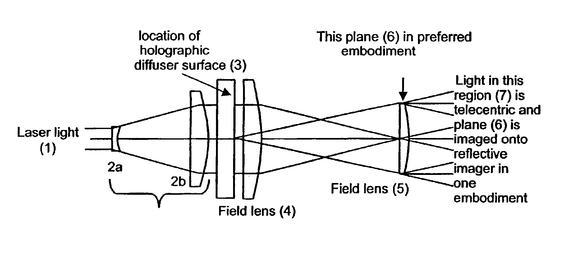
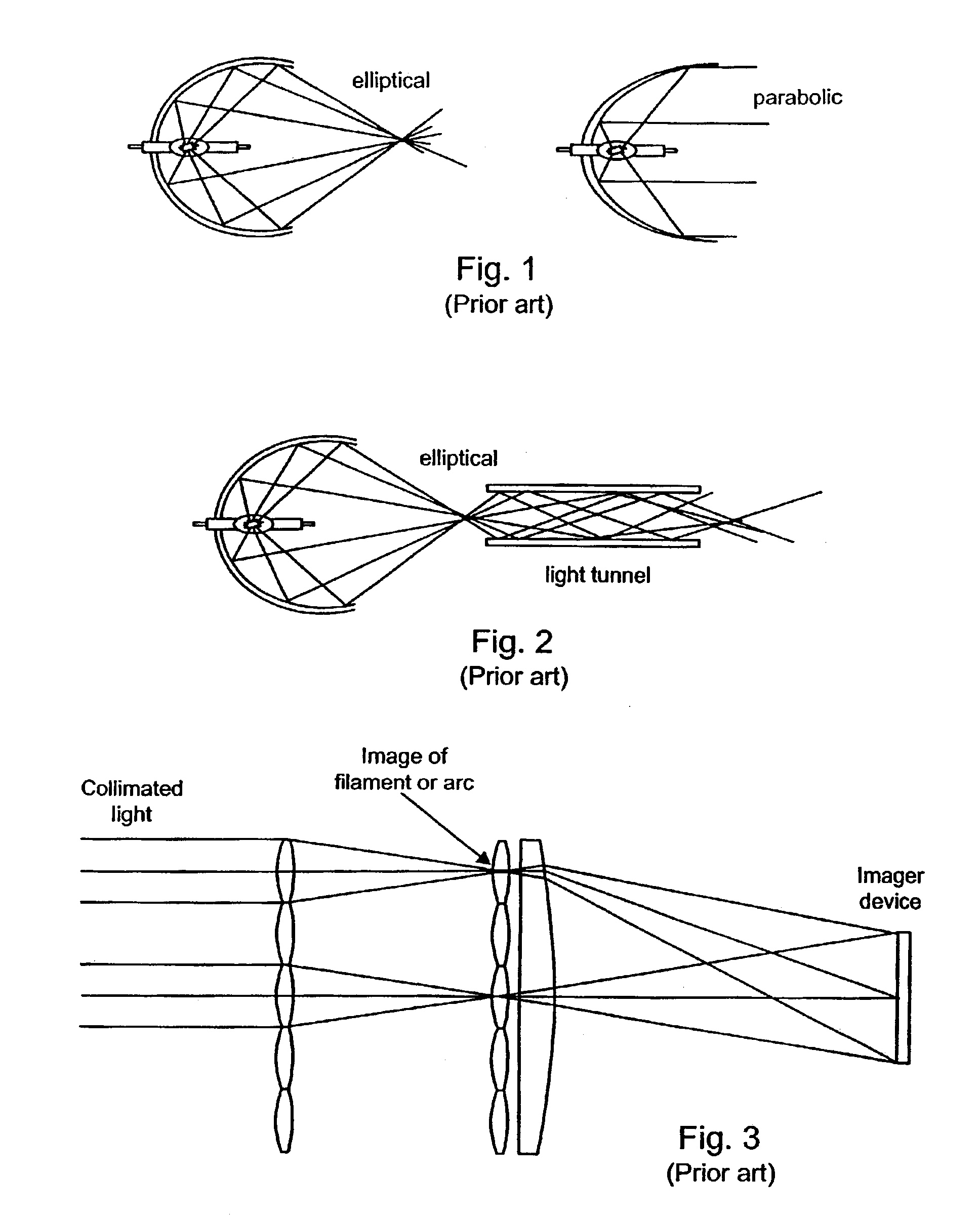
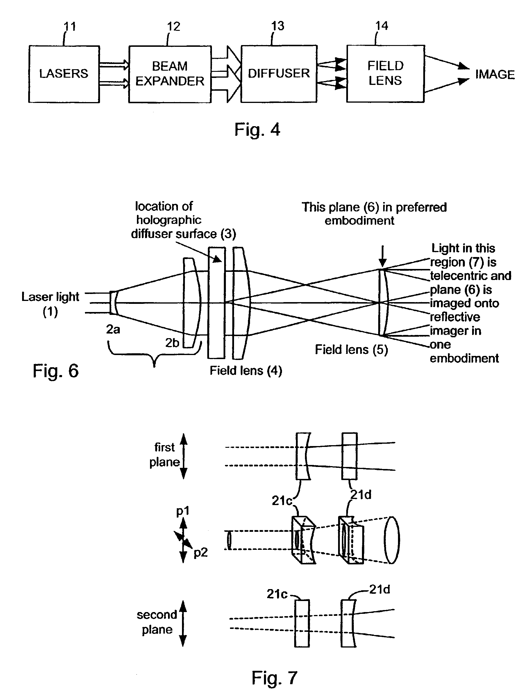
Referring to FIG. 6, a preferred embodiment of the invention is shown. The invention comprises a laser light source 1, a beam expansion and collimating section 2, a holographic diffuser 3, a first field lens 4, and a second field lens 5. In this embodiment, all elements are coaxially centered. The function of the optical processing by the component elements is to convert the incoming substantially collimated round Gaussian laser beam to a uniform rectangular illumination plane 6 for use in illuminating a spatial light modulator such as a liquid crystal d...


PUM

PropertyMeasurementUnit
diameteraaaaaaaaaa
widthaaaaaaaaaa
diameteraaaaaaaaaa

Abstract

Systems and methods for providing illumination suitable for imaging devices such as laser projection systems. In one embodiment, a highly collimated (e.g., laser light) beam is passed through a holographic diffuser to create a well defined cone angle for the light emanating from each point on the diffuser. This light is focused into an illumination image that is controlled by the prescription of the diffuser. In one embodiment, the image is a uniformly intense rectangle having a 4:3 aspect ratio to match an imager for a projection display. The diffuser prescription and resulting illumination image can be selected to match any desired imager. The present systems and methods may provide the advantages of high level of light efficiency, reduction or elimination of speckle and “worminess” and reduction or elimination of cosine4 and gaussian intensity falloff, all of which are common in prior art designs.

Description

FIELD OF THE INVENTIONThe invention relates to projection displays and more particularly an improved method of homogenizing and formatting the light from a light source to produce higher uniformity and efficiency in the projected image.DESCRIPTION OF RELATED ARTIllumination systems used for image projectors are designed to generate a spatially uniform plane which can be used to illuminate an imaging device, film or other media. The reflected or transmitted light from the imaging device is then projected onto a screen for viewing. The brightness and spatial brightness uniformity should be within certain limits for each particular application to be considered acceptable to the viewers.Image projectors including film movie projectors, slide projectors, electronic liquid crystal and micro-electro-mechanical (mem) projectors, microfilm and overhead projectors all require a high degree of spatial light uniformity in the image to produce a pleasing image. This has always been a challenge f...

Claims


Application Information

Patent Timeline
Patent Type & Authority Patents(United States)
IPC IPC(8): A61C1/00H04N9/31H04N5/74C02F1/50G02B27/00
CPCA61C1/0061G02B5/0252H04N9/3197H04N5/7441H04N9/3129H04N9/3152H04N9/3161C02F1/505C02F2103/026G02B5/32
Inventor KAPPEL, DAVIDFISCHER, ROBERT E.TADIC-GALEB, BILJANA
Owner FLIR SYSTEMS TRADING BELGIUM BVBA
Why Eureka
Try Eureka