Liquid-phase growth process and liquid-phase growth apparatus

a growth process and liquid-phase technology, applied in the direction of crystal growth process, chemistry apparatus and processes, polycrystalline material growth, etc., can solve the problem of difficult to grow a high-quality single crystal film on the substrate, difficult to prevent solvent vapor from going around to reach the substrate, and adverse effect of liquid-phase epitaxial growth on said substra

Inactive Publication Date: 2005-03-29
CANON KK
View PDF2 Cites 34 Cited by
  • Summary
  • Abstract
  • Description
  • Claims
  • Application Information

AI Technical Summary

Benefits of technology

An object of the present invention is to provide a liquid-phase growth process which enables to efficiently form a high quality epitaxial film while restraining vaporization of the solvent, at a reasonable cost.
It is preferred that the substrate holder which retains the substrate is made to be rotatable so that together with the rotation of the substrate holder, the capping member intermeshed thereto can be rotated.

Problems solved by technology

It is known that when the solvent of a solution used for liquid-phase epitaxy is vaporized to deposit on a substrate before said substrate is immersed in said solution, an adverse effect is affected on liquid-phase epitaxial growth on said substrate.
Particularly, Kumatoriya et al. describes that in the case where a magnetic garnet single crystal film is grown on a base substrate by way of liquid-phase epitaxial growth from a solution comprising a solvent comprising PbO and B2O3 in which garnet constituent elements are dissolved, by making said solution to be in a supercooled state and immersing said substrate in said solution, there will be occurred a problem in that before the substrate is immersed in the solution, the substrate is directly exposed to vapor of PbO and the like vaporized from the solution where precipitates chiefly of PbO and the like are deposited on the substrate and this exerts an adverse effect which make it difficult to grow a high quality single crystal film on the substrate.
However, the method of Kumatoriya et al. is still problematic in that because the baffle plates are retained on a substrate holder together with the substrate, it is difficult to prevent the solvent vapor from going around to reach the substrate.
In addition to this, there is also a problem such that when the substrate is kept in a stand-by condition without being situated in the growth chamber, the solvent is vaporized to deposit on the inner wall face of the growth chamber so as to become a source which absorbs water and the like, where such source is liable to affect an adverse effect to the growth of the crystal film on the substrate.
In addition, the method of Kumatoriya et al. has a disadvantage such that as the solvent is vaporized, a new solvent is necessitated to be suitably supplemented and this invites an increase in the production cost and a decrease in the productivity of a product.
Besides, in the case where an element whose melting point is low such as Ga is used as a solvent or a solute when a semiconductor crystal film is grown in accordance with the method of Kumatoriya et al., when the substrate is kept in a stand-by condition without being situated in the growth chamber, such element whose melting point is low is rapidly vaporized, where it is difficult to make the semiconductor crystal film to be grown on the substrate such that the composition of the semiconductor crystal film is uniform in every batch or the semiconductor crystal film is uniformly doped in every batch.
However, there is a problem in this case such that when prior to the step of immersing said substrate in said indium solution, said indium solution may evaporate to deposit indium on the surface of the substrate, where the flattened layer of the porous surface of the substrate is resorped due to the deposited indium such that the porous layer is exposed to bring about a growth defect in the structure of said silicon single crystal film grown on the substrate.

Method used


Image

  • Liquid-phase growth process and liquid-phase growth apparatus
  • Liquid-phase growth process and liquid-phase growth apparatus
  • Liquid-phase growth process and liquid-phase growth apparatus

Examples


example

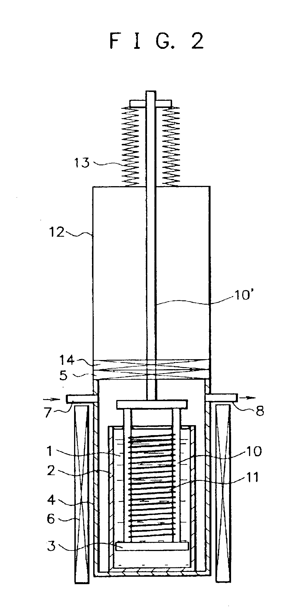
This example describes a preferred embodiment of the liquid-phase growth process in the case of forming a silicon single crystal film using the liquid-phase growth apparatus shown in FIG. 2.

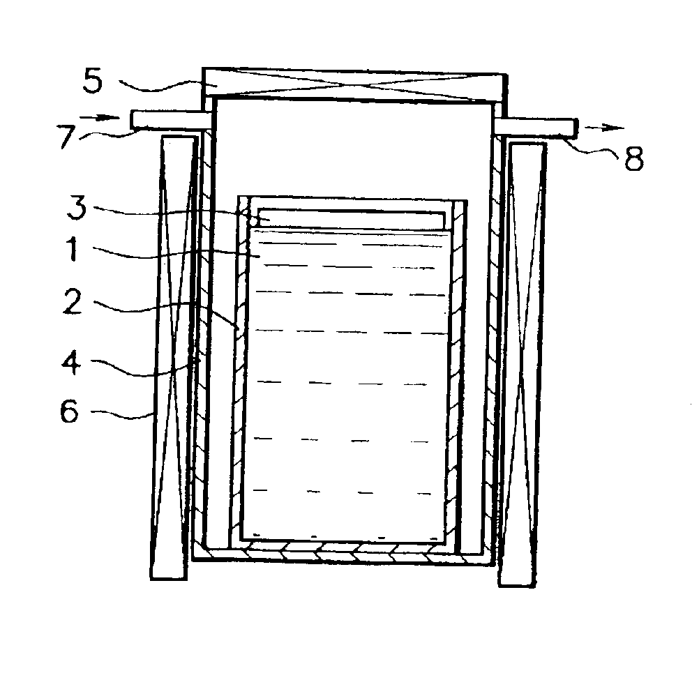
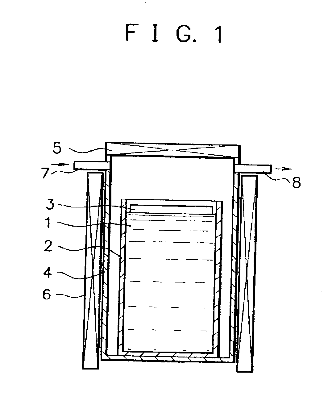
The inside of the growth chamber 4 is maintained with a hydrogen gas atmosphere.

A mixture comprising 11 kg of indium (In) and 1 Kg of gallium (Ga) is accommodated in the crucible 2 which is made of quartz and has an inner diameter of 180 mm. Then, 35 g of silicon (Si) is dissolved in the mixture accommodated in the crucible 2 at a temperature of 930° C. to obtain a saturated solution, followed by elevating the temperature of the saturated solution to a temperature of 923° C. to obtain a supersaturated solution as the solution 1.

On the liquid surface of the solution 1, a member made of quartz which has a diameter of 178 mm and a thickness of 5 mm as the capping member 3 is kept afloat.

In the substrate holder 10 positioned in the load lock chamber 12, a plurality of p+ silicon substrates having a d...


PUM

PropertyMeasurementUnit
temperatureaaaaaaaaaa
inner diameteraaaaaaaaaa
temperatureaaaaaaaaaa

Abstract

A liquid-phase growth process comprising immersing a base substrate in a solution containing reactant species to be grown dissolved therein which is accommodated in a crucible and growing a crystal film on said substrate, characterized in that a capping member is kept afloat on the surface of said solution before said substrate is immersed in said solution and said capping member is subsided in said solution upon immersing said substrate in said solution. A liquid-phase growth apparatus suitable for practicing said liquid-phase growth process.

Description

BACKGROUND OF THE INVENTION1. Field of the InventionThe present invention relates to a liquid-phase growth process of immersing a base substrate in a heated solution containing reactant species to be grown dissolved therein and gradually cooling said solution to epitaxially grow said reactant species on said substrate and an apparatus suitable for practicing said liquid-phase growth process.2. Related Background ArtIt is known that when the solvent of a solution used for liquid-phase epitaxy is vaporized to deposit on a substrate before said substrate is immersed in said solution, an adverse effect is affected on liquid-phase epitaxial growth on said substrate.Japanese Laid-open Patent Publication No. 5(1993)-330983 (Kumatoriya et al.) describes such adverse effect and a method for preventing said adverse effect from being brought about. Particularly, Kumatoriya et al. describes that in the case where a magnetic garnet single crystal film is grown on a base substrate by way of liqui...

Claims


Application Information

Patent Timeline
Patent Type & Authority Patents(United States)
IPC IPC(8): C30B19/06C30B19/00C30B29/06H01L21/208
CPCC30B19/062C30B19/068Y10T117/10Y10T117/1024
Inventor MIZUTANI, MASAKINAKAGAWA, KATSUMISAITO, TETSUROSHOJI, TATSUMIYOSHINO, TAKEHITONISHIDA, SHOJI
Owner CANON KK
Why Eureka
Try Eureka