

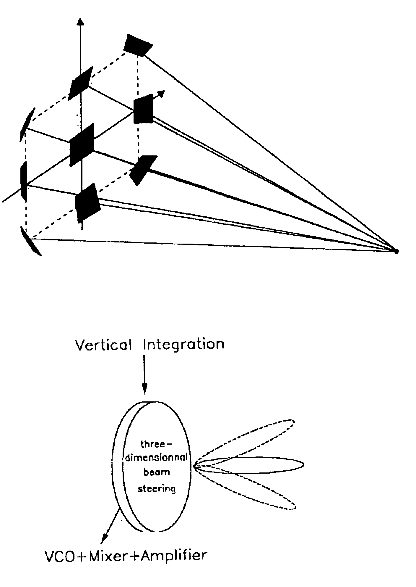
3-dimensional beam steering system
a beam steering and beam technology, applied in the direction of individual energised antenna arrays, resonant antennas, radiating element structural forms, etc., can solve the problems of extremely limited output power of millimeter wave-generating devices, complex millimeter wave technology, and use of millimeter waves, so as to reduce electrical characteristics, increase receiving power, and manufacturing process simple
- Summary
- Abstract
- Description
- Claims
- Application Information
AI Technical Summary
Benefits of technology
Problems solved by technology
Method used
Image

Examples
Embodiment Construction
A preferred embodiment of the present invention will be described hereinafter with reference to the accompanying drawings.
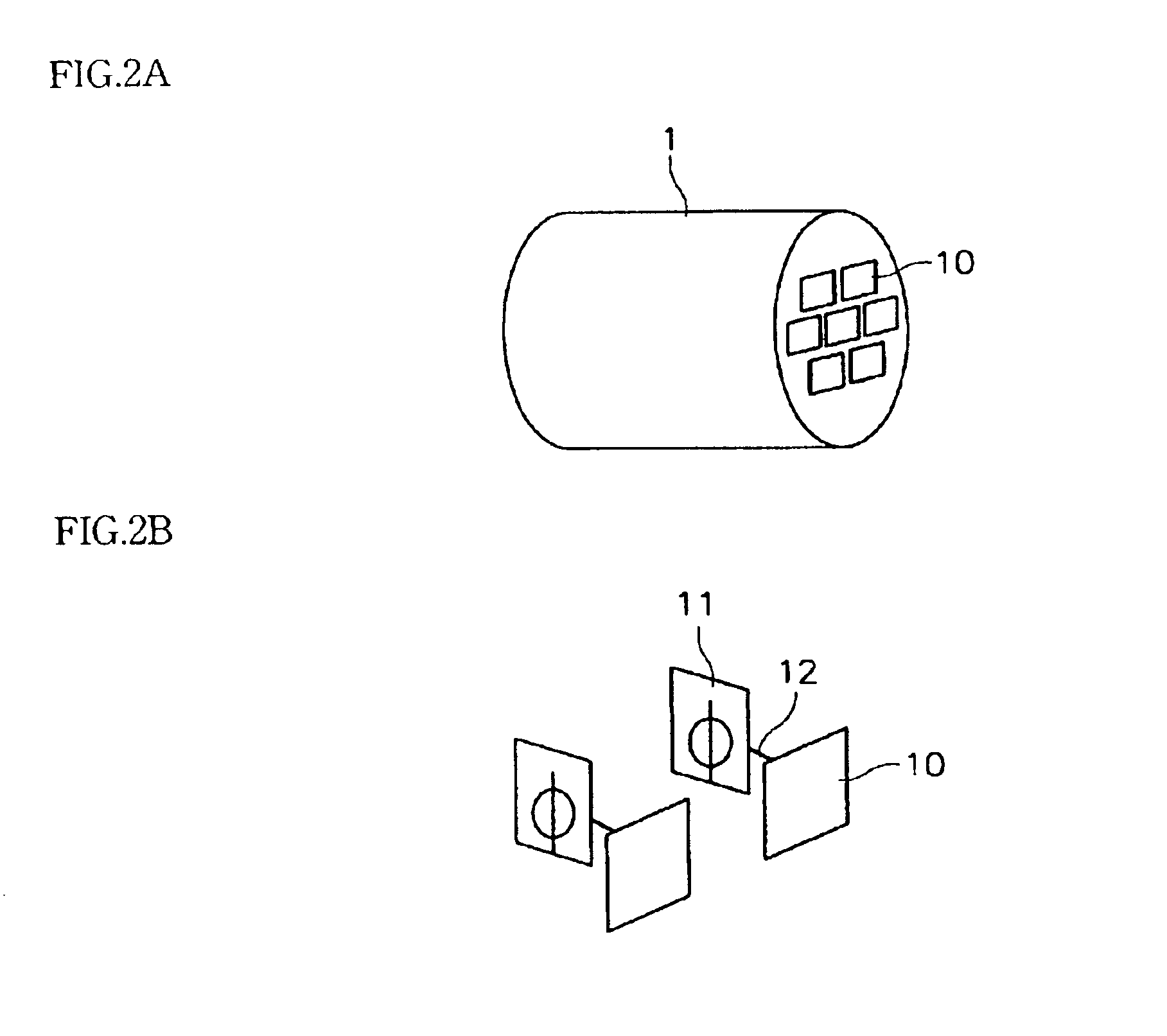
FIG. 2a is a perspective view illustrating a 3-dimensional beam focusing antenna system.
As shown in FIG. 2a, an antenna system 1 has a cylindrical contour and includes a plurality of antenna elements 10 on a front surface thereof. Even though seven antenna elements 10 are arranged in a matrix form in this embodiment, the number and formation of the antenna elements 10 can be changed or modified. For example, ten antenna elements can be concentrically arranged.
FIG. 2b shows an antenna element of the 3-dimensional antenna system of FIG. 2a.
The antenna element 10 includes a driving unit 12 for 3-dimensionally rotating the antenna element 10, and a phase shifter 11 for controlling the phase of a signal to transmit through the antenna element 10.
The antenna elements 10 and the driving unit 12 are integrally manufactured using a micro-electro-mechanical system (MEMS) ...
PUM
 Abstract
Description
Claims
Application Information