Fiber-optic sensing system for distributed detection and localization of alarm conditions

a fiber optic sensor and distributed technology, applied in the field of fiber optic systems, can solve the problems of inability to provide cost effective solutions for widely acceptable applications of distributed fiber optic sensors, inability to fully integrate the in-fiber weakly reflective bragg gratings of the optical fiber sensing network, and failure of physical structures, etc., to achieve the effect of simple and inexpensiv

Inactive Publication Date: 2005-04-05
CICESE CENT DE INVESTIGACION CIETIFICA Y DE EDUCACION SUPERIOR DE ENSENADA B C
View PDF26 Cites 87 Cited by
  • Summary
  • Abstract
  • Description
  • Claims
  • Application Information

AI Technical Summary

Benefits of technology

An object of the invention is to provide a simple and inexpensive optical fiber sensor system for distributed detection and loca...

Problems solved by technology

However, it is well recognized that complete sensing systems based on in-fiber weakly reflective Bragg gratings which includes optical fiber sensing network, signal demodulation and demultiplexing subsystems are still quite expensive.
The combination of light sources and high-sensitive detectors capable of multi-band high-resolution spectral analysis or/and complex time or frequency domain reflectometry does not yet provide cost effective solution for widely acceptable applications of distributed fiber optic sensors.
Failure in physical structures begins, as a rule, in a small fashion and increases with time.
However, this approach does not allow a simple locating the multiple disturbances.
In particular, there are no convenient and economical means for determining the location of static or slowly varying disturbance along the extensive sensing loop.
Although the microbend sensor could provide a simple solution for many applications and has capability for locating a disturbance by using OTDR technique, this method suffers from a high level of loss...

Method used


Image

  • Fiber-optic sensing system for distributed detection and localization of alarm conditions
  • Fiber-optic sensing system for distributed detection and localization of alarm conditions
  • Fiber-optic sensing system for distributed detection and localization of alarm conditions

Examples


Embodiment Construction

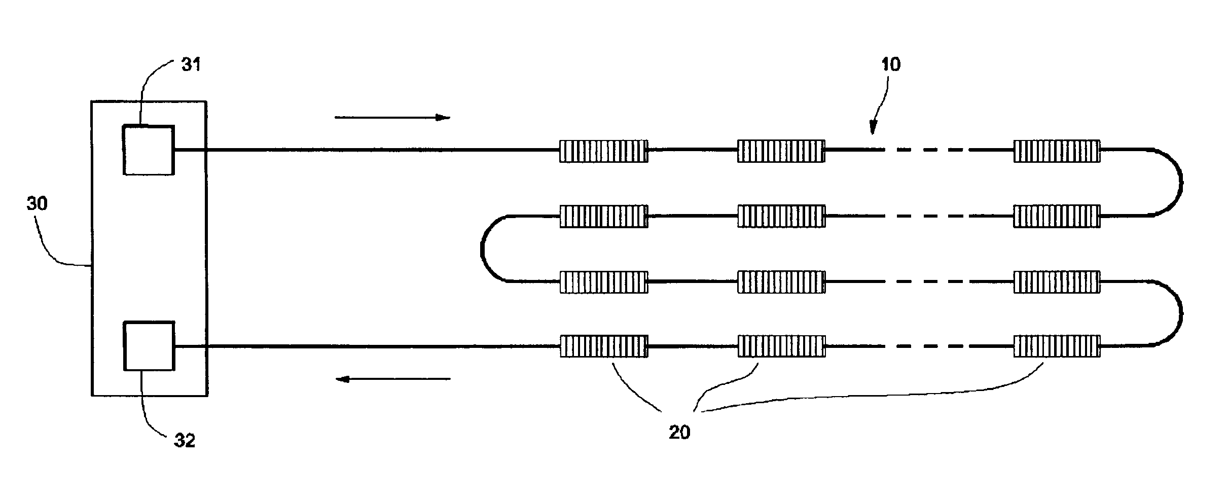
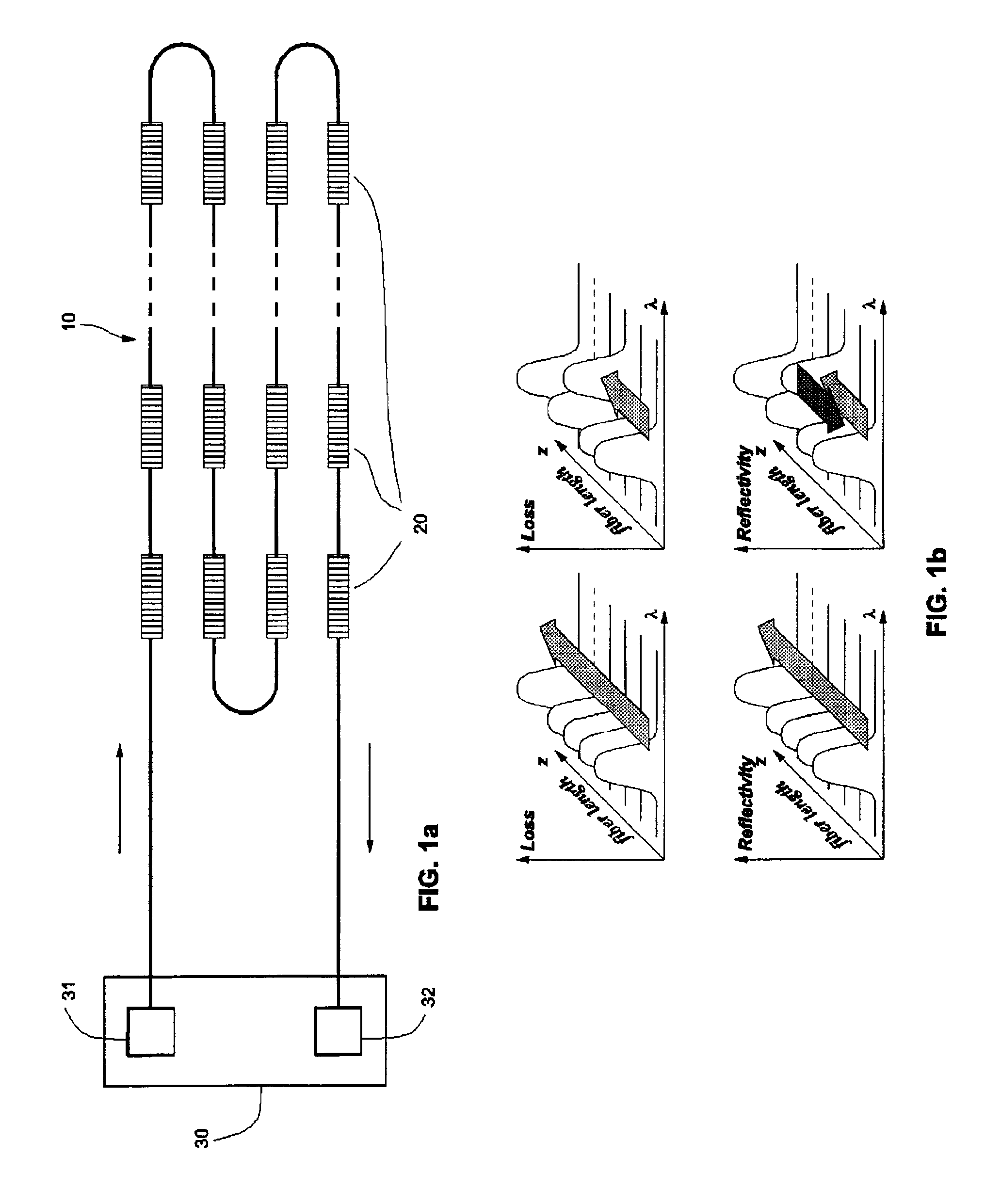
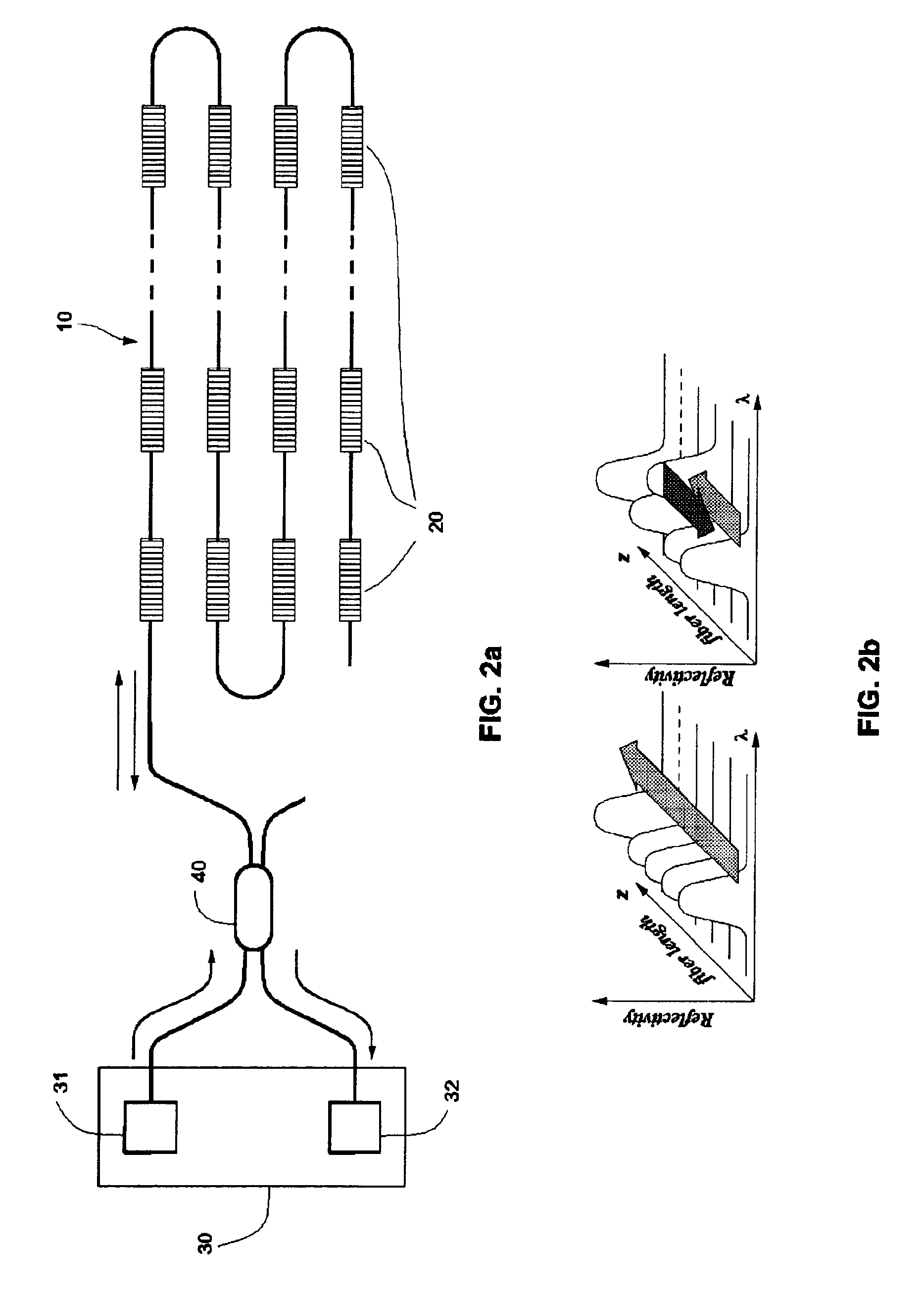
In the present invention, fiber optic systems based on an array of equal spectrally selective sensing elements, whose characteristic bands can shift under external influence, are described. The spectrally selective sensing elements may be coupled optically with the optical fiber or may be written onto the fiber as fiber Bragg gratings or fiber long period gratings. In normal undisturbed conditions characteristic bands of sensing elements occupy limited wavelength range further called as first wavelength range. The present invention utilizes a light source and optical power detector to monitor transmittance or reflection of the fiber within a wavelength range which further called as second wavelength band and which does not overlap with the first wavelength range. Detected change of fiber transmittance or reflection in the second wavelength range may be used to set off an alarm signal and to perform a localization of the alarm area.

FIG. 1a shows one embodiment of the system disclosed...


PUM


Abstract

An optical fiber sensor system comprising of an optical fiber including plurality of sensitive elements, each sensitive element has characteristic spectral band which in normal undisturbed condition lies in a first wavelength range and, under an influence of some specified condition to be detected, shifts to a second wavelength range; first and second wavelength ranges do not overlap. Means for probing an optical transmission or reflection of the fiber operate within second wavelength range to monitor the changes of the transparency or reflectivity of the fiber caused by the shift of characteristic spectral band into the second wavelength range.
The invention provides means for distributed monitoring of equipment or construction structures and detection of specified conditions and can provide alarm signal when the specified conditions become effective.

Description

BACKGROUND1. Field of the InventionThis invention relates to fiber optic systems for early detection and location of mechanical, thermal, and other disturbances. In particular, it relates to such systems, which are used for structural monitoring of large structures and for detecting and locating fluid presence.2. Description of Prior ArtFiber optic sensors become attractive innovation with applications in many areas of industry and engineering. Optical fiber, due to its properties, can play roles of both sensitive element and signal delivery channel. Especially distributed fiber optics sensors are suitable for monitoring of large pieces of equipment such as planes, ships, factory equipment, pipelines, and construction structures like buildings, bridges, etc.In recent years, many fiber optic sensing systems were developed using in-fiber Bragg gratings. Bragg gratings have narrow reflection spectral bands whose position within the optical spectrum depends on certain conditions, like t...

Claims


Application Information

Patent Timeline
IPC IPC(8): G01M3/04G01D5/353G01D5/26G01M11/08G02B6/02G02B6/34
CPCG01D5/35303G01M3/047G01M11/086G02B6/2932G02B6/022
Inventor CHLIAGUINE, MIKHAILSPIRINE, VASSILIMIRIDONOV, SERGUEIJIMENEZ, FRANCISCO JAVIER MENDIETAABENCHUCHAN, ENRIQUE MITRANI
Owner CICESE CENT DE INVESTIGACION CIETIFICA Y DE EDUCACION SUPERIOR DE ENSENADA B C
Why Eureka
Try Eureka