
High temperature superconductor tunable filter having a movable substrate controlled by a magnetic actuator

a superconductor and actuator technology, applied in the field of hts filters, can solve the problems of corresponding compromise in filter steepness or selectivity, limited dynamic range, undesirable intermodulation products, etc., and achieves large tuning range, low friction and backlash (hysteresis).

Inactive Publication Date: 2005-04-05
SUPERCONDUCTOR TECHNOLOGIES INC
View PDF15 Cites 17 Cited by
  • Summary
  • Abstract
  • Description
  • Claims
  • Application Information

AI Technical Summary

Benefits of technology

The present invention also includes methods of inducing the circulating supercurrents within a “poled” HTS reaction plate of a push-pull magnetic actuator. In one method, the magnetic driver is cooled below its critical temperature while the HTS reaction plate is above its critical temperature and the HTS reaction plate and the magnetic driver are in close proximity. A drive current is then induced in the magnetic driver while the HTS reaction plate is cooled below its critical temperature, thereby inducing the circulating supercurrents within the continuous strip of HST material to “pole” the “poled” HTS reaction plate. To assist cooling the magnetic driver below its critical temperature while the magnetic driver is in close proximity to a HTS reaction plate above its critical temperature, the magnetic driver may be constructed from HTS material that has a higher critical temperature than the HTS material used to construct the HTS reaction plate. Alternatively, both the magnetic driver and the HTS reaction plate may be brought below their critical temperatures. Then, a heat source above an upper surface of the movable substrate may generate radiant energy to briefly raise the HTS reaction plate above its critical temperature without raising the magnetic driver above its critical temperature while a drive current is applied to the magnetic driver coil.
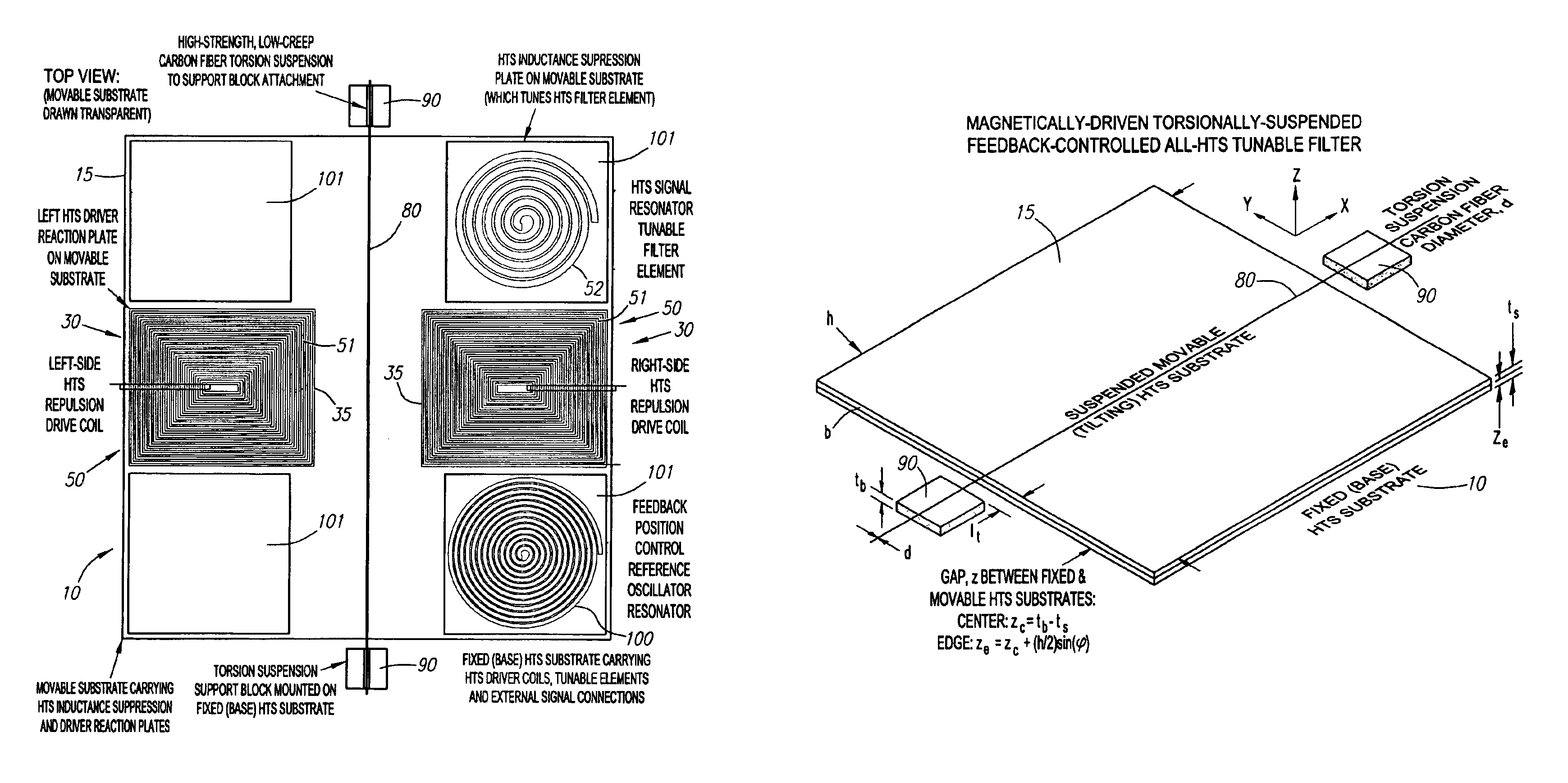
In an another embodiment, the movable substrate is suspended on a torsionally compliant fiber or band. The torsion fiber attaches to and extends across the upper surfaice of the movable substrate. Preferably, the torsion fiber is positioned on a centerline of the movable substrate such that, absent additional forces, the lower surface of the suspended movable substrate is parallel to the upper surface of the fixed substrate. The torsion fiber may be attached to posts on the fixed substrate that are laterally disposed to the movable substrate. A first and a second magnetic actuator are located on opposite sides of the torsion fiber. Rotational motion of the torsionally suspended movable substrate is induced in one direction when current is passed through the driver coil on one side of the torsion fiber axis, and in the opposite direction when the current is passed through the opposing driver on the other side of the rotational axis. In a preferred embodiment, to allow a greater tuning range, the movable substrate comprises a first and a second planar portion attached to each other in a dihedral configuration, the torsion fiber axis being located near the apex of the dihedral angle. This dihedral angle allows the rotational axis of the movable substrate to be placed very close to the fixed substrate, while still permitting rotation of the movable substrate by an angle slightly greater than the dihedral angle without either of the sides of the movable substrate striking the fixed substrate. The dihedral configuration allows a planar portion of the movable substrate to go from a tuning position parallel to, and in very close proximity to, the fixed substrate, to a rotated position in which the end of the planar portion is a comparatively large distance from the fixed substrate (and angled away from it by the dihedral angle). This enables a very large tuning range to be achieved in either capacitive or inductive tuning (or combinations of these in complex resonator structures). In an alternate embodiment, the movable substrate comprises a first planar portion and a second planar portion wherein the first and second planar portions are joined with a lap joint. The torsion fiber would attach to the movable substrate adjacent the lap joint.
While the use of a rotationally compliant torsion fiber or band suspension has been described here, a number of different mechanical means to constrain the position of the axis of rotation of the movable substrate to obtain very low friction and backlash (hysteresis), and nearly-pure rotational motion of the movable substrate could be utilized in this embodiment of the invention. These include a fulcrum or knife edge on the movable substrate working against a flat surface, or a groove or other suitable positioning structure on the fixed substrate, a fulcrun or knife edge on the fixed substrate working against a flat surface, or a groove or other suitable positioning structure on the movable substrate, or the combination of one of these with a torsion fiber or band to assist in maintaining proper positioning of the movable substrate and its rotational axis.

Problems solved by technology

In most filter technologies, achieving a low insertion loss requires a corresponding compromise in filter steepness or selectivity.
While varactors are simple and robust, they have limited Q's, and suffer from the problem that the linear process that tunes them extends all of the way to the signal frequency, so that high-amplitude signals create, through the resulting nonlinearities, undesirable intermodulation products and other problems.
Unfortunately, this also leads to a serious associated disadvantage: limited dynamic range.
Unfortunately, for high signal amplitudes, this parametric modulation of the capacitance can produce severe cross-modulation (IM) effects between different signals, as well as harmonic generation and other undesirable effects.
While these signal-frequency varactor capacitance variations are the basis of useful devices such as parametric amplifiers, subharmonic oscillators, frequency multipliers, and many other useful microwave circuits, in the signal paths of conventional receivers they are an anathema.
As long as the εr (E) relationship applies out to the signal frequency, then the presence of the signal as a component of E will lead to the same intermodulation problems that the varactors have.
In addition to the intermodulation / dynamic range problems of varactors, these conventional tuning devices also have serious limitations in Q, or tuning selectivity.
An additional problem with both varactors and “tunable materials” for circuits with high values of Q is that these are basically two-terminal devices; that is, the dc tuning voltage must be applied between the same two electrodes to which the signal voltage is applied.
However, while the design of bias circuits that limit the loss of energy to a percent, or a fraction of a percent of the resonator energy is not difficult, even losses of a fraction of a percent are not nearly good enough for very high Q circuits (e.g., Q's in the 103 to >105 range, as achievable with HTS resonators).
In addition to their freedom from intermodulation / dynamic range problems, normal metal plate MEMS variable capacitor structures offer the potential for substantially lower losses and higher Q's.
While this conventional MEMS variable capacitor structure is capable of improved Q's and avoids the intermodulation problems of varactors and “tunable materials”, it has some potential problems of its own.
For example, the electrostatic force attracting the two plates is quite weak, except at extremely short range.
In this parallel-plate MEMS capacitor configuration, if a linear spring provides the restoring force between the plates, when the bias voltage is increased such that the gap separation has dropped to ⅓ of the separation at zero bias, the plate motion becomes unstable and the plates snap together.
Further, the short-range nature of the electrostatic force makes its use in variable-inductance tuning even more problematic because of the requirement for very narrow gaps (to give reasonable levels of force at reasonable drive voltages), since much larger gaps (e.g., hundreds of microns) are desirable in devices having such variable-inductance tuning.
Although coating the plates with a thin dielectric and allowing progressive contact of thin curved (stress-bent) layers with a fixed electrode as voltage is increased may counteract the short-range effect of this electrostatic force (and with proper drive plate shaping, extend the tuning range in capacitance beyond 3:1), triboelectric (i.e., charging due to friction) and charge transfer effects under the high field condition tend to give significant hysteresis in the capacitance-voltage (C-V) characteristics of these “window shade” MEMS devices.
In addition, there are other potential problems in conventional MEMS devices.
This means that for such phase sensitive applications, the tunable elements must achieve levels of repeatability, hysteresis and continuity that appear difficult to achieve in ferroelectric piezoelectric actuators, let alone “window shade” electrostatic MEMS devices.

Method used


Image

  • High temperature superconductor tunable filter having a movable substrate controlled by a magnetic actuator
  • High temperature superconductor tunable filter having a movable substrate controlled by a magnetic actuator
  • High temperature superconductor tunable filter having a movable substrate controlled by a magnetic actuator

Examples


Embodiment Construction

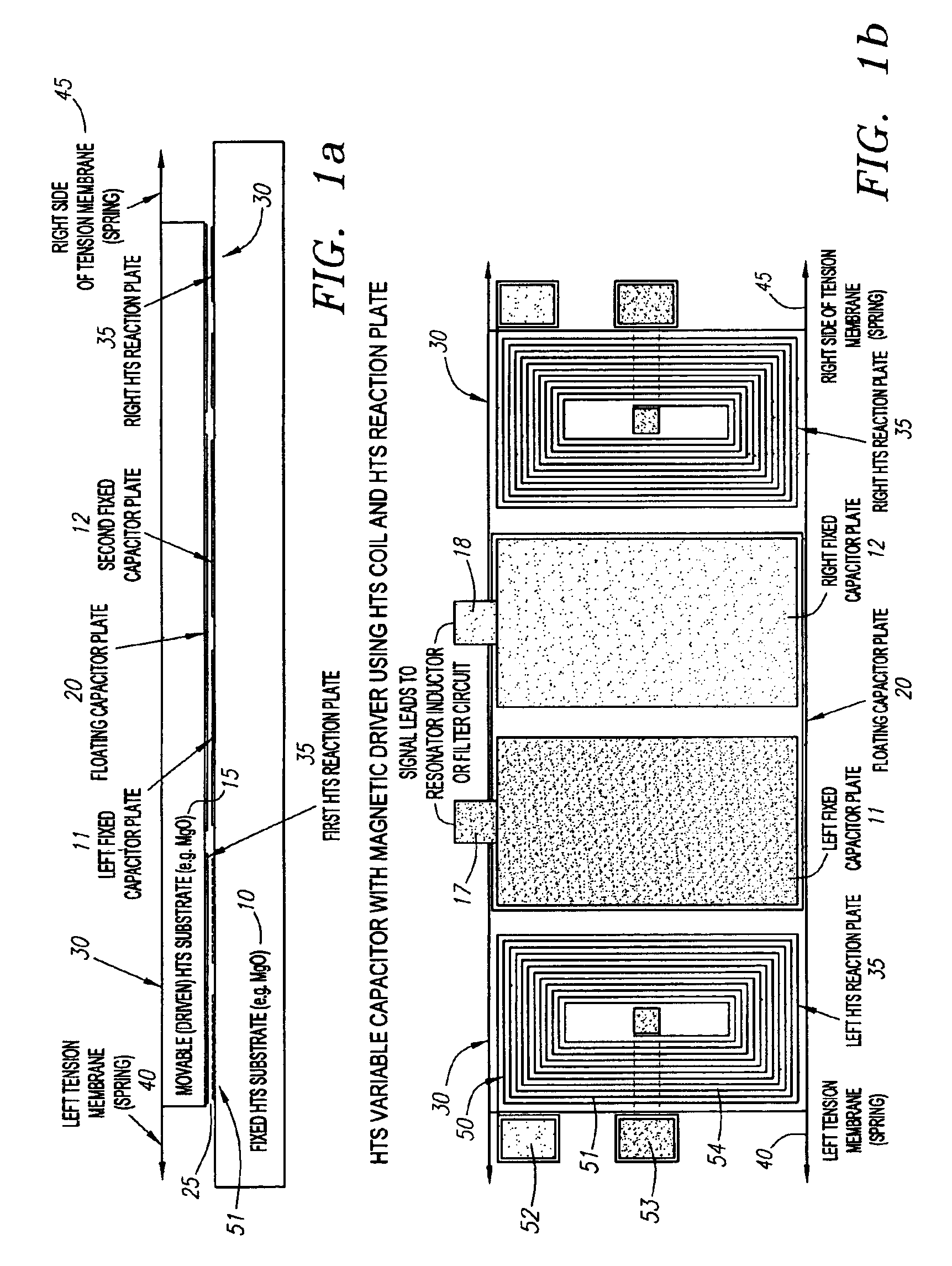
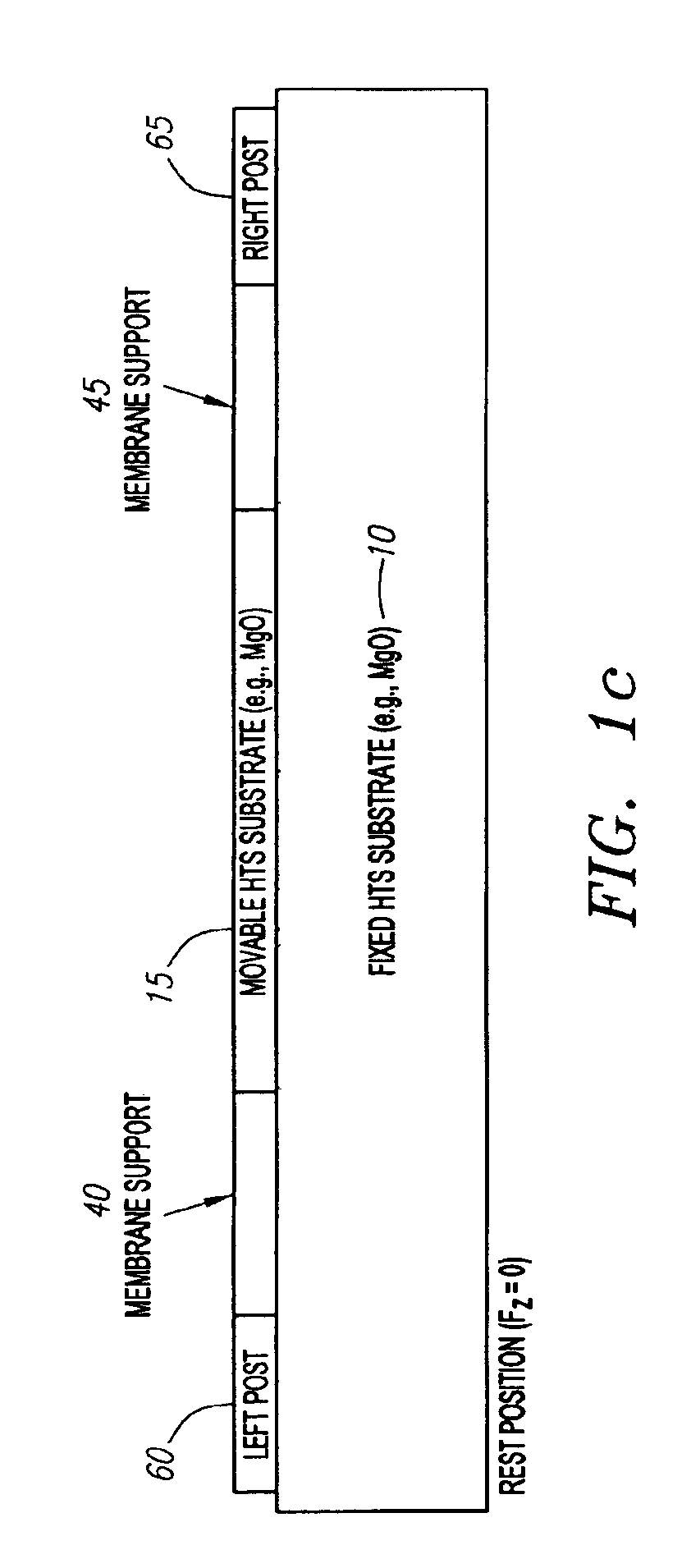
The present invention provides a magnetic actuator for varying the electrical characteristics of variable capacitors or inductors. The magnetic actuator of the present invention has a dramatically greater tuning range than the electrostatic drivers of conventional prior art MEMS variable capacitors. Turning now to FIGS. 1a through 1c, a variable parallel split-plate capacitor tuned by a pair of magnetic actuators with a movable substrate 15 having a membrane-suspended vertical translational geometry is illustrated. The variable capacitor comprises a fixed substrate 10 (illustrated in FIGS. 1a and 1c) suitable for carrying an HTS layer. Suitable materials for the fixed substrate 10 include MgO. On the upper surface of the fixed substrate 10, a first fixed capacitor plate 11 and a second fixed capacitor plate 12 are formed using thin-film HTS material. Such epitaxial superconductive thin films are now routinely formed and commercially available. See, e.g., R. B. Hammond, et al., “Epit...


PUM

PropertyMeasurementUnit
repulsive forceaaaaaaaaaa
thicknessaaaaaaaaaa
temperature superconductoraaaaaaaaaa

Abstract

A circuit is provided wherein the electronic properties of the circuit are varied by a magnetic actuator. The circuit includes a fixed substrate and a movable substrate. The magnetic actuator comprises a magnetic driver on an upper surface of the fixed substrate that is substantially overlapped by an HTS reaction plate on the lower surface of the fixed substrate. A tuning current applied through a continuous strip of HTS material in the magnetic driver induces a repulsive magnetic force causing the movable substrate to move with respect to the fixed substrate.

Description

FIELD OF THE INVENTIONThis invention relates to a high temperature superconductor (HTS) tunable filter. More particularly, this invention relates to an HTS filter tunable by actuating a magnetic driver.BACKGROUND OF THE INVENTIONThe need for a high-quality factor (Q), low insertion loss tunable filter pervades a wide range of microwave and RF applications, in both the military, e.g., RADAR, communications and Electronic Intelligence (ELINT), and the commercial fields such as in various communications applications, including cellular. Placing a sharply defined bandpass filter directly at the receiver antenna input will often eliminate various adverse effects resulting from strong interfeing signals at frequencies near the desired signal frequency in such applications. Because of the location of the filter at the receiver antenna input, the insertion loss must be very low to not degrade the noise figure. In most filter technologies, achieving a low insertion loss requires a correspond...

Claims


Application Information

Patent Timeline
Patent Type & Authority Patents(United States)
IPC IPC(8): H01P1/203H01P1/20
CPCH01P1/20Y10S505/705Y10S505/70
Inventor EDEN, RICHARD C.
Owner SUPERCONDUCTOR TECHNOLOGIES INC
Learn More