Method and device for minimizing oil consumption in a gas turbine engine

a gas turbine engine and oil consumption technology, which is applied in the direction of liquid fuel engines, machines/engines, mechanical equipment, etc., can solve the problems of increasing the level of engine emissions, affecting the performance of the engine, and inevitably consuming a portion of conventional design oil, so as to prevent oil leakage, minimize oil consumption, and high density and viscosity

Inactive Publication Date: 2005-04-12
PRATT & WHITNEY CANADA CORP
View PDF20 Cites 30 Cited by
  • Summary
  • Abstract
  • Description
  • Claims
  • Application Information

AI Technical Summary

Benefits of technology

The invention provides a method of minimizing oil consumption in a gas turbine engine, by avoiding reliance on air intake into the engine oil circuit bearing chamber for oil-sealing purposes. Typically a gas turbine engine has an oil supply circuit to cool and lubricate bearings supporting one or more engine shafts with bearing chambers enveloping the bearings and containing oil that is sprayed or splashed on the moving parts. Oil is circulated to and evacuated from the bearing chamber with an oil pressure pump, scavenge pump, oil filter, oil tank and is cooled within a heat exchanger. No oil-air separator is needed however since hydropad seals are used between the shaft and bearing chambers that do not rely no air intake flow to maintain an oil seal but rather rely on centrifugal casting of oil away from the sealing surfaces during rotation. Oil has a relatively high density and viscosity compared to air and therefore rotation of the seal casts oil radially outward preventing oil leakage. Reducion of air intake has several advantages including: reducion of oil-air mixing; elimination of air-oil separator and the resultant oil loss through exhausted aerosols; reduction in pump, oil tank and oil cooler size due to volume reduction.

Problems solved by technology

This conventional design inevitably consumes a portion of the oil which must be made up from oil supplies in the oil circuit.
Oil aerosols have been the cause of increased level of engine emissions and staining of the engine nacelle surfaces.

Method used


Image

  • Method and device for minimizing oil consumption in a gas turbine engine
  • Method and device for minimizing oil consumption in a gas turbine engine
  • Method and device for minimizing oil consumption in a gas turbine engine

Examples


Embodiment Construction

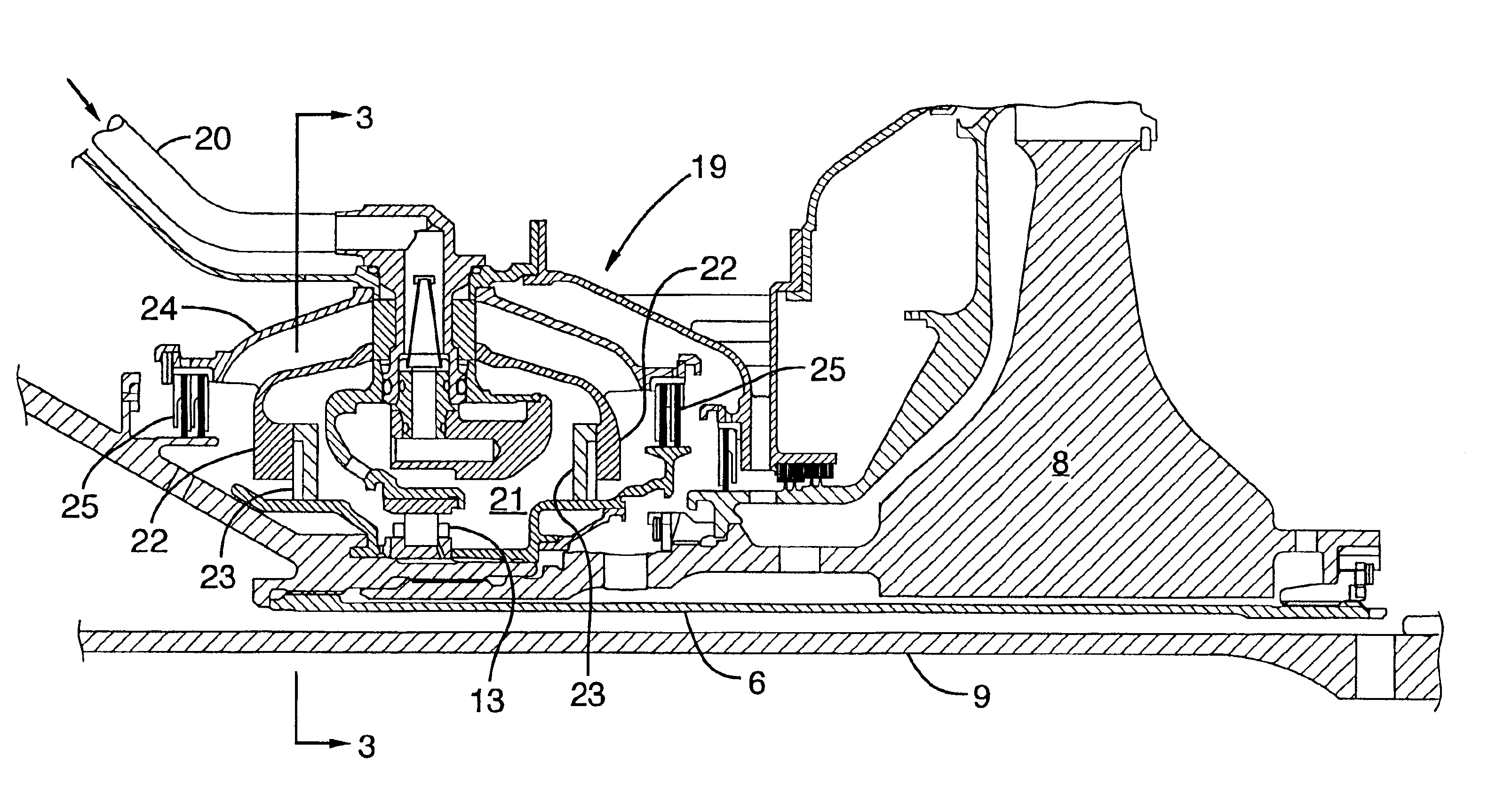
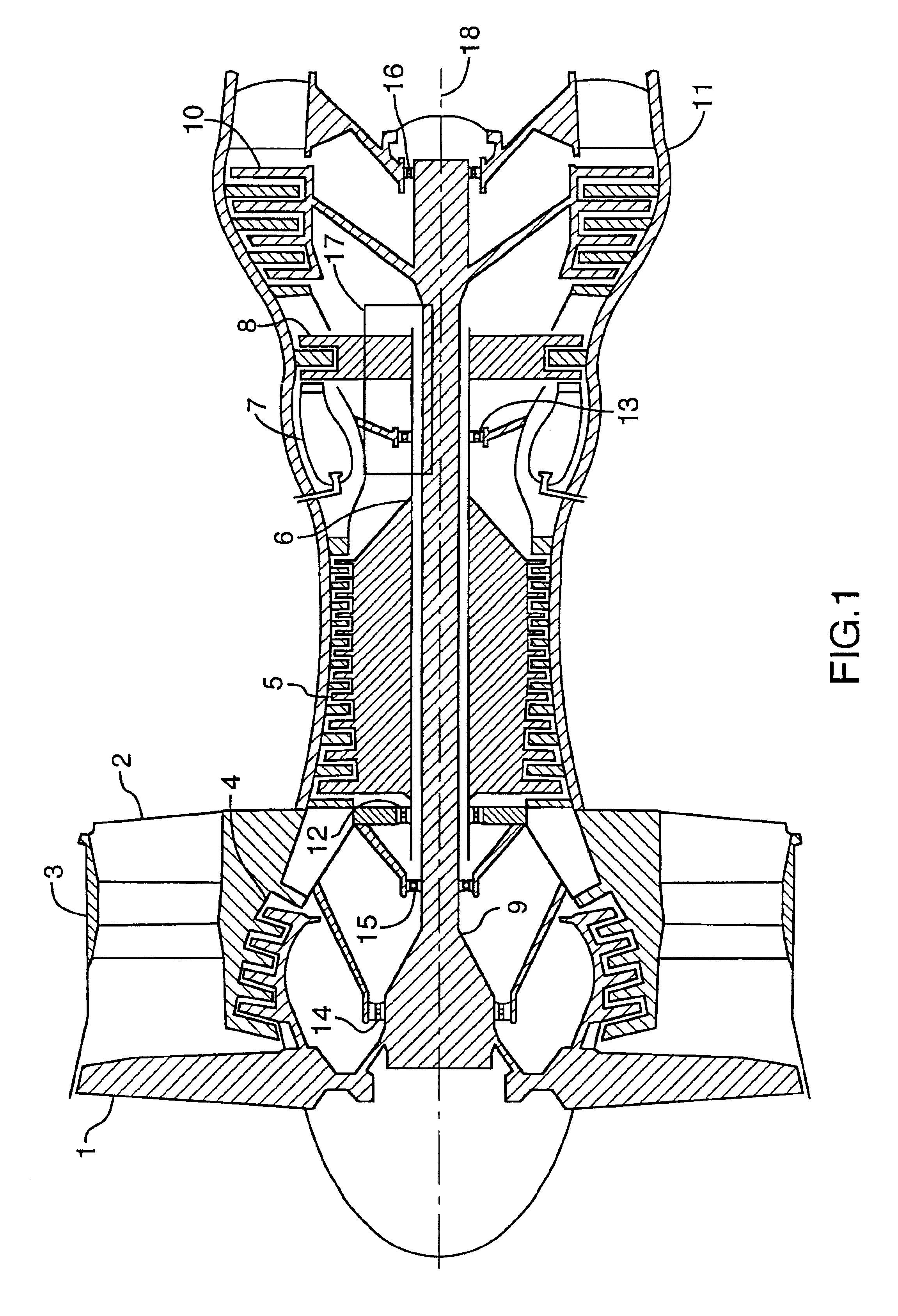
FIG. 1 shows a longitudinal cross-sectional view through an example gas turbine engine. Air passes through the engine (from left to right as drawn) first passing fan 1 and then splitting into two flows of air. An outer portion of the air flow passes through the bypass duct 2 formed by the annular fan case 3 and an inner portion passes through the engine core past low pressure compressor blade 4. In the example shown, the engine includes an axial high pressure compressor 5 mounted to a high pressure shaft 6 and driven by hot gas passing from combustor 7 over high pressure turbine rotors 8. The fan 1 and low pressure compressor 4 are mounted to a low pressure shaft 9 driven by low pressure turbine rotors 10. As seen in FIG. 1, the high pressure shaft 6 is supported on forward bearings 12 and rearward bearings 13. In a like manner, the low pressure shaft 9 is supported on three bearings 14, 15 and 16.

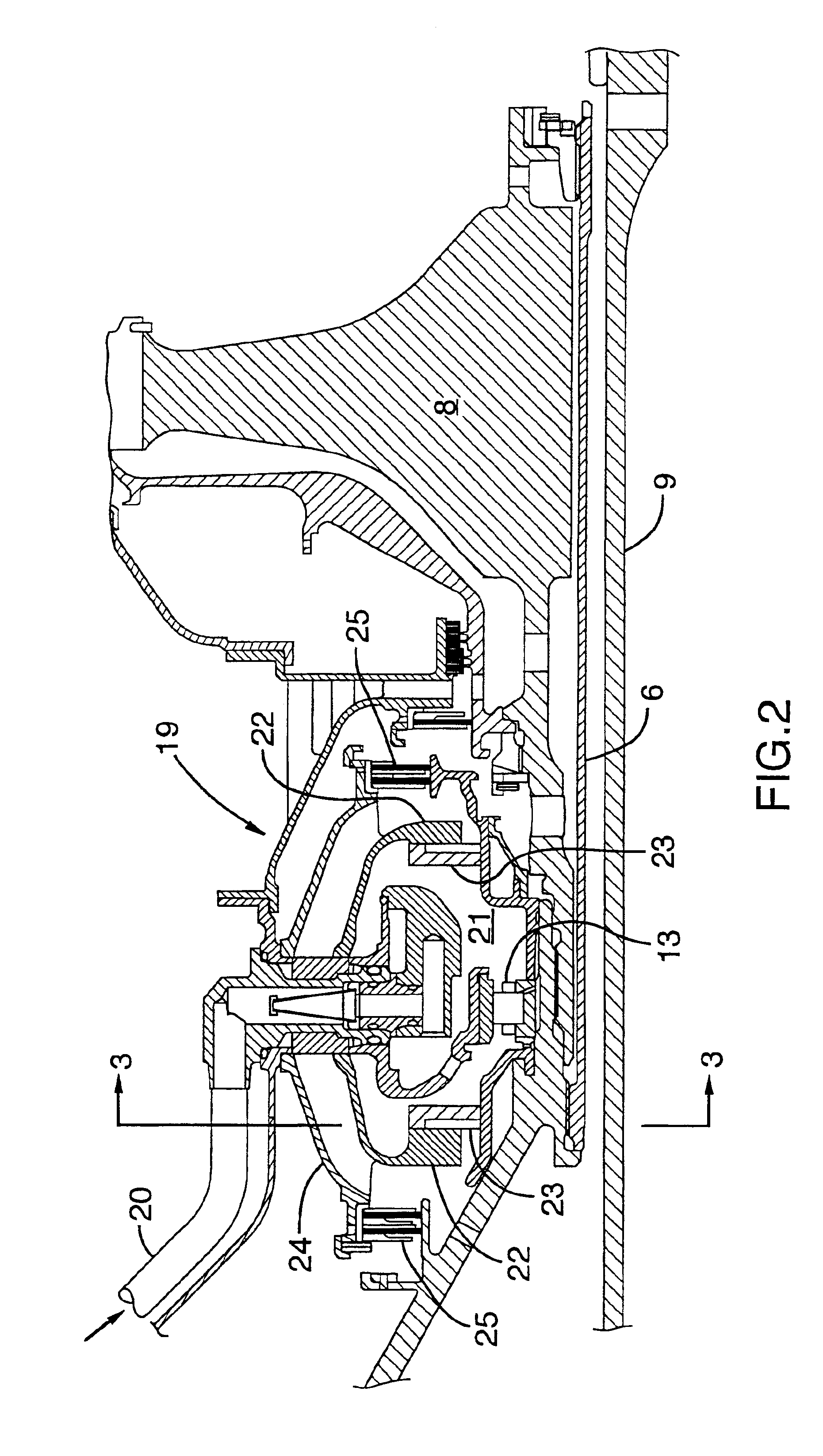
Of particular interest to the present invention are the bearing cavities which surroun...


PUM


Abstract

A method of minimizing oil consumption in a gas turbine engine, by avoiding reliance on air intake into the engine oil circuit for bearing chamber oil sealing purposes. The engine oil circuit has bearing chambers with hydropad seals between the shaft and bearing chamber. During engine operation the ring rotates to cast oil radially outwardly from the shaft axis toward the outer periphery of the bearing chamber under centrifugal force, independent of any gas pressure differential across the sealing surfaces of the hydropad seal.

Description

TECHNICAL FIELDThe invention relates to a method of minimizing or completely reducing oil consumption in a gas turbine engine, and an engine designed according to the method, by avoiding the traditional reliance on air intake into the bearing chambers for preventing oil leakage.BACKGROUND OF THE ARTThe invention provides a method of minimizing oil consumption in a gas turbine engine. In general, oil is consumed as a consequence of air flow into the engine oil circuit to create a vacuum condition in the bearing oil chambers, thus preventing oil leakage into the compressed air and gas path of the engine. Since air is drawn into the bearing chambers to oppose oil leakage flow and the air mixes with the oil, an oil-air separator is necessary to reconstitute the oil and exhaust the air. Oil is consumed in that the air exhausted from the oil-air separator contains oil residue in an aerosol form. This conventional design inevitably consumes a portion of the oil which must be made up from o...

Claims


Application Information

Patent Timeline
Patent Type & Authority Patents(United States)
IPC IPC(8): F01D25/18F01D25/00
CPCF01D25/183
Inventor LIU, XIAOLIU
Owner PRATT & WHITNEY CANADA CORP
Why Eureka
Try Eureka