

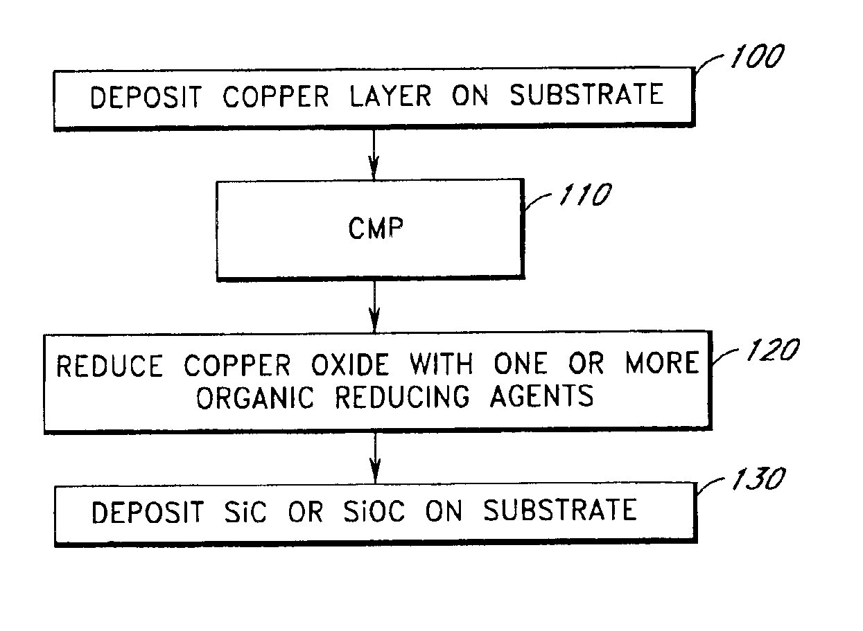
In situ reduction of copper oxide prior to silicon carbide deposition
a technology of silicon carbide and copper oxide, which is applied in the direction of special surfaces, semiconductor/solid-state device manufacturing, electrical equipment, etc., can solve the problems of loss of etch selectivity, high leakage current and/or adhesion, and lower resistance during dry-etching and cmp processes
- Summary
- Abstract
- Description
- Claims
- Application Information
AI Technical Summary
Benefits of technology
Problems solved by technology
Method used
Image

Examples
example 1
Reduction of CuO with Methanol Vapor
A silicon substrate having a copper oxide coating on copper metal is loaded into the reaction chamber of an Eagle 10™ reactor. The reaction chamber is evacuated to vacuum and heated to 360° C. The pressure of the reaction chamber is adjusted to about 5-10 mbar with flowing nitrogen gas.
Methanol vapor is mixed with nitrogen gas, introduced to the reaction chamber and contacted with the substrate.
Excess methanol and reaction by-products are purged from the reaction chamber by flowing nitrogen gas. A layer of silicon carbide is deposited over the copper layer by PECVD in the same reaction chamber.
example 2
Reduction of CuO with Ethanol Vapor
A silicon substrate having a copper oxide coating on copper metal is loaded into the reaction chamber of an Eagle 10™ reactor. The reaction chamber is evacuated to vacuum and heated to 360° C. The pressure of the reaction chamber is adjusted to about 5-10 mbar with flowing nitrogen gas.
Ethanol vapor is mixed with nitrogen gas, introduced to the reaction chamber and contacted with the substrate.
Excess ethanol and reaction by-products are purged from the reaction chamber by flowing nitrogen gas. A layer of silicon carbide is deposited over the copper layer by PECVD in the same reaction chamber.
example 3
Reduction of CuO with 2-Propanol Vapor
A silicon substrate having a copper oxide coating on copper metal is loaded into the reaction chamber of an Eagle 10™ reactor. The reaction chamber is evacuated to vacuum and heated to 360° C. The pressure of the reaction chamber is adjusted to about 5-10 mbar with flowing nitrogen gas.
2-propanol (also known as isopropanol) vapor is mixed with nitrogen gas, introduced to the reaction chamber and contacted with the substrate.
Excess 2-propanol and reaction by-products are purged from the reaction chamber by flowing nitrogen gas. A layer of silicon carbide is deposited over the copper layer by PECVD in the same reaction chamber.
PUM
 Abstract
Description
Claims
Application Information