Array comprising diamond-like glass film
a technology of diamond-like glass and arrays, applied in the direction of library member identification, sequential/parallax process reactions, electrical/magnetic measurement arrangements, etc., can solve the problems of many methods of manufacturing arrays on glass, high cost, and difficult to obtain samples and reagents, etc., to achieve high detection signal strength and high surface area
- Summary
- Abstract
- Description
- Claims
- Application Information
AI Technical Summary
Benefits of technology
Problems solved by technology
Method used
Image
Examples
example 1
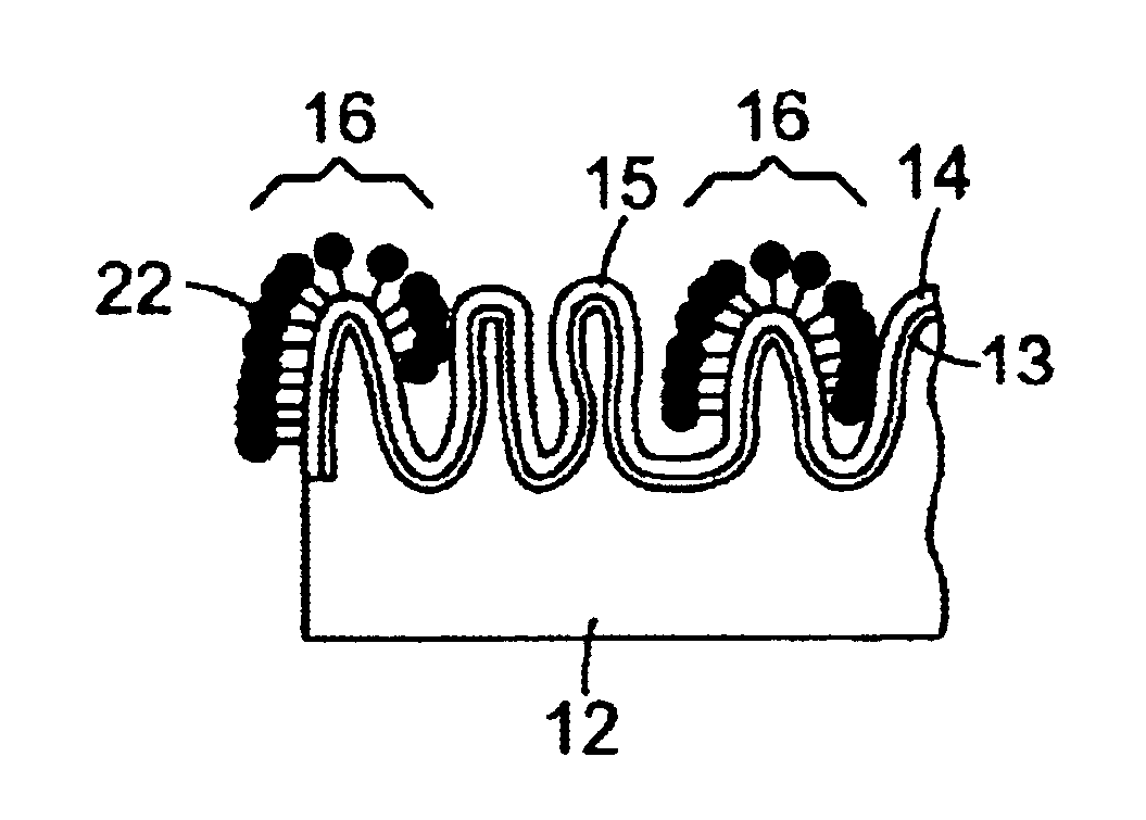
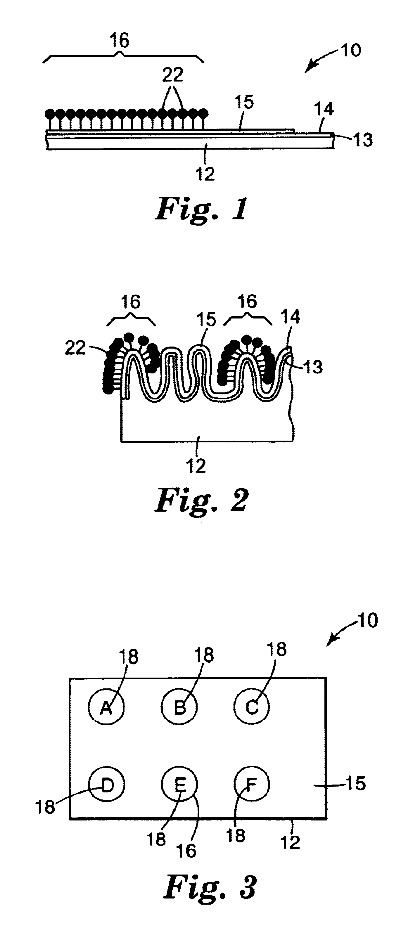
[0136]This example illustrates the application of glass-like (DLG) thin films to an oriented polyethylene shrink film.
[0137]Four samples containing DLG films on shrink films, Samples A-D, were prepared in a commercial Plasmatherm (Model 2480) reactive ion etcher powered by an adjustable 3 kWatt RF power supply and matching network operating at a frequency of 13.56 MHz. The system was pumped by a 5.4 m3 / min (200 cfm) roots blower backed by a mechanical pump to a base pressure of less than 10 mTorr before starting the runs.
[0138]Plasma treatment was done in three steps in all the runs. The flow rate of the process gases was maintained with either a needle valve or a mass flow controller. Chamber pressure was measured by using a capacitance manometer. In the first step, samples of 1-mil heat shrink polyethylene film (available as Cryovac D955 from Sealed Air Corporation, Saddle Brook, N.J.) were mounted on a 22-inch circular powered electrode and were primed with a pure oxygen plasma t...
example 2
[0143]This example illustrates additional methods for the derivatization of DLG films on substrates.
[0144]A silylation solution (Solution A) was prepared by diluting 4 mL of 3-aminopropyltriethoxysilane (APTES) with 36 mL of 95:5 v / v ethanol / water. A second solution (Solution B) was similarly prepared by diluting 4 mL of 3-glycidoxypropyltri-methoxysilane (GPTMS) with 36 mL of the ethanol / water mixture.
[0145]Unshrunk square pieces of Sample 1B, about 60 mm by 60 mm, were placed in each of two petri dishes and covered with Solution A or Solution B, respectively. These were allowed to stand, with occasional agitation, for 1 hour. The pieces were then rinsed thoroughly with ethanol and allowed to air-dry. The treated films (i.e., those with DLG films thereon), labeled Sample E and Sample F, respectively, were characterized by infrared surface analysis utilizing a Perkin-Elmer 16PC FT-IR equipped with a Multiple Internal Reflection (MIR) Accessory and a 45° crystal of KRS-5. By comparis...
example 3
[0147]This example illustrates affixation of DNA to samples of modified DLG on polyethylene shrink film prepared in the previous examples.[0148]A) A 500 bp cDNA was prepared and purified by standard PCR techniques. This was then radiolabeled with 33P using a commercial kit to provide a labeled cDNA solution of approximately 0.5 ng / μl. A series of standards was prepared from this solution by spotting triplicate 1.0 μl spots each at 1×, 0.1×, and 0.01× concentration on polylysine coated glass microscope slides (Newcomer Supply, Middleton, Wis.). Four 1.0 μl spots at 1× concentration were spotted on a piece of Sample E and allowed to dry. The spotted film was then washed with 1% SDS solution, followed by DI water, and dried. The film and standards were imaged using a Packard Cyclone™ Phosphorimager. Analysis of the images obtained indicated that approximately 30% of the spotted cDNA had been immobilized on the Sample E film. This film was then placed on a hot plate with a surface tempe...
PUM
| Property | Measurement | Unit |
|---|---|---|
| Nanoscale particle size | aaaaa | aaaaa |
| Time | aaaaa | aaaaa |
| Time | aaaaa | aaaaa |
Abstract
Description
Claims
Application Information
 - R&D
- Intellectual Property
- Life Sciences
- Materials
- Tech Scout
- Unparalleled Data Quality
- Higher Quality Content
- 60% Fewer Hallucinations
Browse by: Latest US Patents, China's latest patents, Technical Efficacy Thesaurus, Application Domain, Technology Topic, Popular Technical Reports.
© 2025 PatSnap. All rights reserved.Legal|Privacy policy|Modern Slavery Act Transparency Statement|Sitemap|About US| Contact US: help@patsnap.com


