Capture range control mechanism for voltage controlled oscillators

Inactive Publication Date: 2005-04-19
ZARLINK SEMICON LTD
View PDF9 Cites 52 Cited by
  • Summary
  • Abstract
  • Description
  • Claims
  • Application Information

AI Technical Summary

Benefits of technology

[0011]The gain between the variation in input voltage variation and the output voltage variation of the buffer is adjusted by means of a resistor. The resistor may be placed off chip to eliminate any dependency on manufacturing tolerances in the fabrication

Problems solved by technology

These methods allow the construction of a VCO that can be adjusted for manufacturing variation in the VCO, and they can compensate for variation in ambient conditions that the circuit is operating in, such as changes in temperature, but they have the drawback of abruptly changing the oscillatio

Method used


Image

  • Capture range control mechanism for voltage controlled oscillators
  • Capture range control mechanism for voltage controlled oscillators
  • Capture range control mechanism for voltage controlled oscillators

Examples


Embodiment Construction

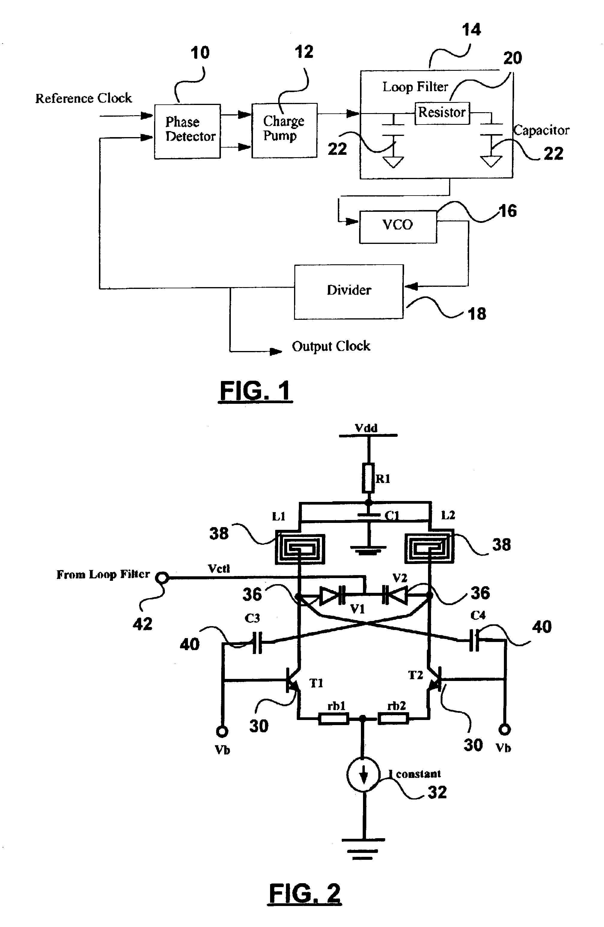
[0020]FIG. 1 is a block diagram of a generic phase locked loop. It comprises a phase detector 10 receiving at its inputs a reference signal and a feedback signal, a charge pump receiving an output of the phase detector 10 which converts detected phase difference to a source or sink current that varies in duration commensurate with the duration of the phase difference, a voltage controlled oscillator 16 whose output is fed back via divider 18 to the input of the phase detector 10. The loop filter 14 comprises resistor 20 and capacitors 22.

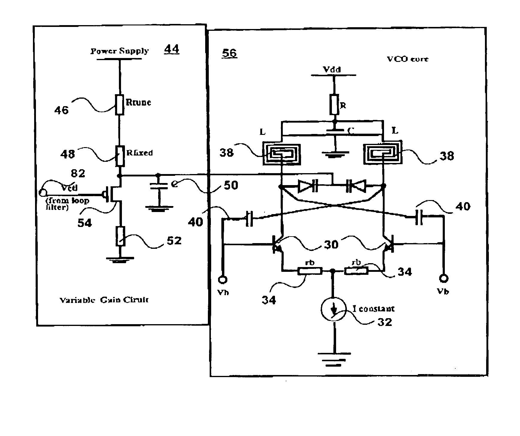
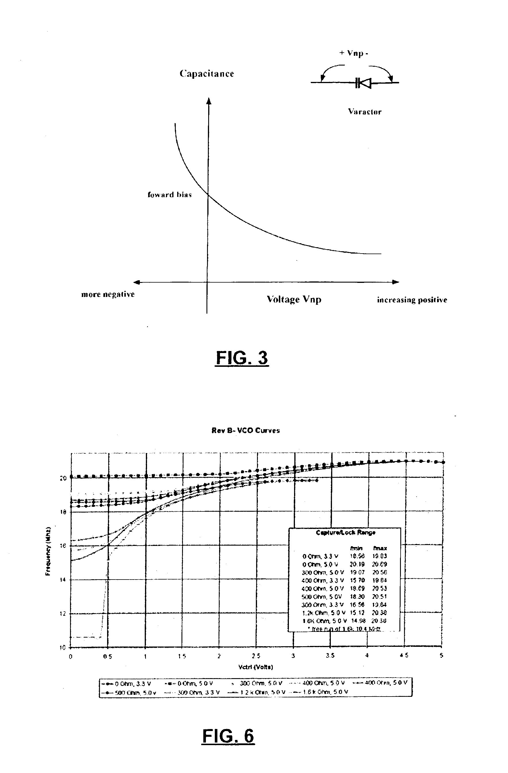
[0021]The voltage controlled oscillator 16 is shown in FIG. 2. This comprises a pair of transistors 30, a constant current source 32, resistors 34, a pair of varactors 36 (variable capacitance capacitors), a pair of inductors 38, and a pair of capacitors 40. Input terminal 42 receives a control voltage Vctl from the loop filter 14. In operation, the control voltage Vctl varies the capacitance of varactors 36 in the LC circuit, and thus varies the ou...


PUM


Abstract

A voltage controlled oscillator generates an output signal whose frequency varies as a first function of a control voltage applied to a control terminal. The voltage controlled oscillator has a wide range of frequency of operation. A gain adjust circuit adjusts the gain of the voltage controlled oscillator such that the first function varies as a second function of the gain. In a preferred embodiment the gain adjust circuit includes a variable impedance that may be external or integrated onto a common chip with the oscillator core.

Description

FIELD OF THE INVENTION[0001]This invention relates to electronic voltage controlled oscillator circuits, for example for use in phase locked loops manufactured as monolithic integrated circuits.BACKGROUND OF THE INVENTION[0002]The frequency of oscillation of an oscillator is typically adjusted with a control voltage. Such an oscillation is referred to as a voltage controlled oscillator (VCO). In some implementations the control voltage varies the current source for one or all of a plurality of inverters connected in series with each other. In other implementations the control voltage varies the capacitance in an inductance / capacitance resonator.[0003]In typical integrated circuit implementations the circuit element which has a capacitance which varies with a control voltage is a collector varactor. This may be a diode employed as a variable capacitor with the variation of junction capacitance dependent on the reverse bias voltage or a MOS varactor in which case the enhancement or de...

Claims


Application Information

Patent Timeline
IPC IPC(8): H03L7/099H03L7/08H03B5/08H03B5/12H03L7/093
CPCH03L7/099H03B5/1209H03B5/1243H03B5/1231H03L7/093
Inventor SINGH, RANJITFOUZAR, YOUCEFSKIERSZKAN, SIMON JOHNABDEL-MAGUID, HAZEM
Owner ZARLINK SEMICON LTD
Why Eureka
Try Eureka