Medical guide wire

a technology of guide wires and wires, applied in the field of medical guide wires, can solve the problems of becoming a great hindrance in treating and curing the diseased area, and achieve the effects of reducing resistance, and improving the directional maneuverability of the head plug

Inactive Publication Date: 2005-04-26
ASAHI INTECC CO LTD
View PDF14 Cites 62 Cited by
  • Summary
  • Abstract
  • Description
  • Claims
  • Application Information

AI Technical Summary

Benefits of technology

[0014]With a technical concept in mind that the head plug advances smoothly into the diseased area of the non-uniform vascular tract in combination with a manipulation of the medical guide wire, the head plug forms a spherical or semi-spherical configuration, and right and left side portions of the head plug are in part undercut to form flat surface portions in order to reduce a resistance that the head plug receives when advancing along the vascular tract, thereby improving a directional maneuverability of the head plug. In order to further improve the directional maneuverability of the head plug, a core line member is rectangular in cross section, longer sides of which position in parallel with the flat surface portion of the head plug.
[0015]According to the medical guide wire thus structured, the length of the front, rigid portion is reduced and the loosely wound portion extended as rearward from the rigid portion is elastically expandable at its line element turns when an outer force is applied to the loosely wound portion. The front distal portion has an elastically workable section which enhances a contact-adaptability and contact-detectability against the diseased area so as to remarkably ameliorate an opera

Problems solved by technology

This becomes a great hindrance to treating and curing the diseased area par

Method used


Image

  • Medical guide wire
  • Medical guide wire
  • Medical guide wire

Examples


first embodiment

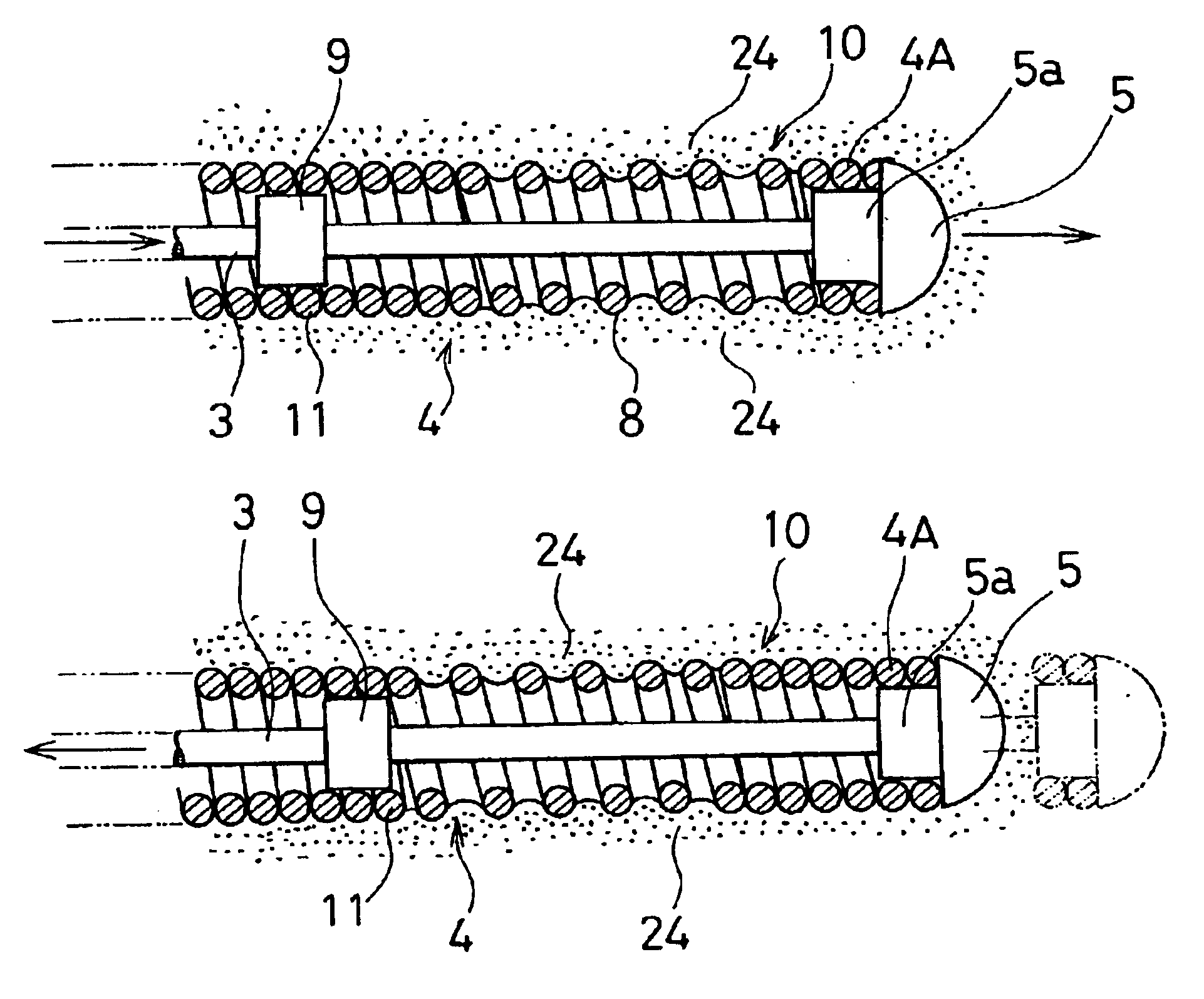
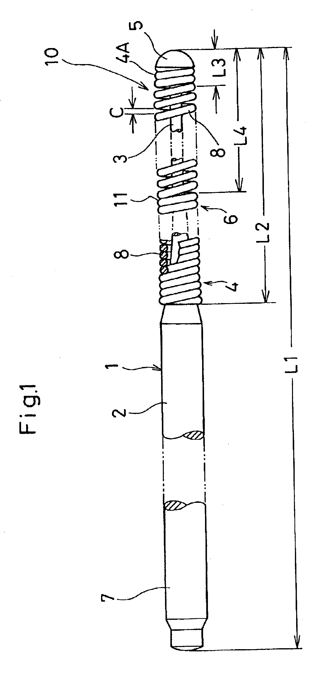
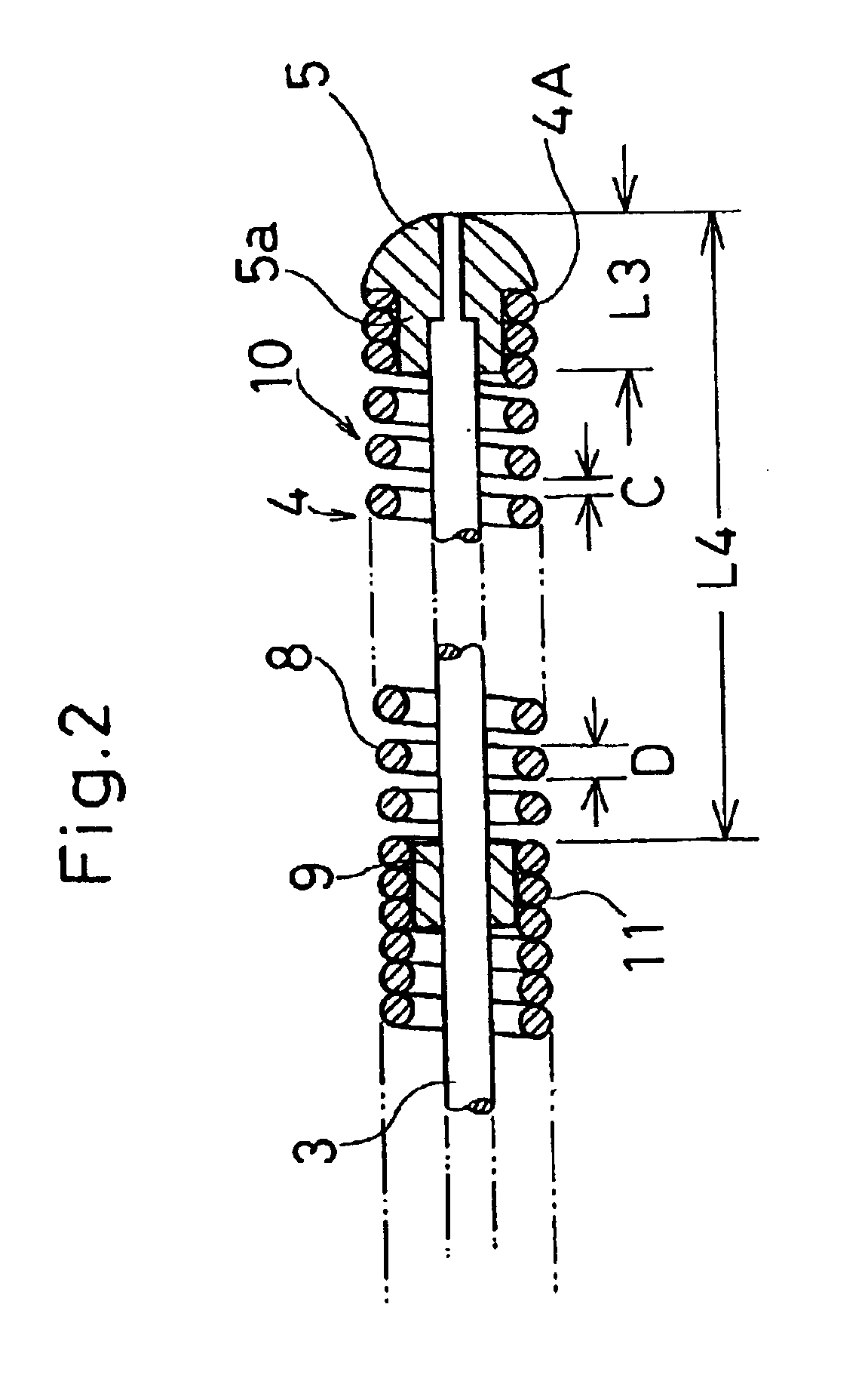
[0033]Referring to FIGS. 1 through 8 which show a medical guide wire 1 (referred to merely as “guide wire” hereinafter) according to the present invention, a core line 3 is formed by thinning a distal end of a main wire portion 2 of a flexible line wire as shown in FIGS. 1 and 2. To a distal end of the core line 3, a spherical or semi-spherical head plug 5 is secured which has a stem portion 5a extended in one piece from a rear surface of the semi-spherical head. Around the core line 3, a helical spring 4 is provided. A front end of the helical spring 4 is firmly interfit to the stem portion 5a of the head plug 5 to have a leading end portion 6 superior in flexibility. In a front distal portion 10 including the head plug 5 and a part of the helical spring 4 extending from the head plug 5, two or three turns of the helical spring 4 is secured to the stem portion 5a of the head plug 5, a length L3 of a rigid portion 4A is 0.5 mm or less which extends from a top of the head plug 5 to a...

second embodiment

[0049]FIGS. 12 and 13 show the invention in which right and left sides of the spherical portion of the head plug 5 are symmetrically undercut along a central line 14 to form flat portions 13 in a parallel direction. The flat portions 13 enable the head plug 5 to an enhanced directional maneuverability when the handling knob 7 is operated. In order to further enhance the directional maneuverability, the flat portions 13 are positioned out of the parallel but arranged such as to render the head plug 5 tapered off in the axial direction. Otherwise, it is preferable that the flat portions 13 are positioned in parallel with longer sides of the core line 3 which is formed rectangular in cross section.

third embodiment

[0050]FIG. 14 shows the invention in which an outer surface of a head plug 5A is roughened instead of machining a mirror finish. The roughened surface of the head plug 5A enables the manipulator to feel an increase contact resistance against the obstruction area P so as to improve an operable feeling.


PUM


Abstract

In a medical guide wire (1), a rigid portion (4A) is located at a distal end of a helical spring (4), and the rigid portion (4A) measures 0.5 mm or less which extends from a top end of a head plug (5) to a rear end of a portion in which the helical spring (4) is secured to the head plug (5), and an intermediary location (11) is secured to an intermediary boss portion (9) of a core line (3) to provide a loosely wound portion (8) from a rear end of the head plug (5) to the intermediary location (11) to be elastically expandable due to a clearence (C) appeared between line element turns of the loosely wound portion (8).

Description

BACKGROUND OF THE INVENTION[0001]1. Field of the Invention[0002]The invention relates to a medical guide wire used upon introducing a catheter into a cardiovascular system or the like.[0003]2. Description of Prior Art[0004]A medical guide wire, in the form of a flexible line wire, is disclosed in Japanese Provisional Publication No. 4-25024 to ensure a safety insertion for a catheter when inserting a balloon catheter into a blood vessel to treat a diseased area such as angiostenosis of the coronary artery or when inserting a thin flexible catheter into the blood vessel for an angiography.[0005]Japanese Laid-open Patent Application No. 3-60674 discloses a medical guide wire in which a core shaft has a ball-like head portion to engage with an open end section of a catheter to prevent its forward movement. The ball-like head portion has an advantage that enables a manipulator to withdraw the guide wire together with the catheter.[0006]As shown in FIG. 15, the medical guide wire 30 is i...

Claims


Application Information

Patent Timeline
IPC IPC(8): A61B5/00A61M25/01A61M25/00A61M29/02A61M25/09
CPCA61M25/09033A61M2025/09183A61M2025/09083
Inventor KATO, TOMIHISAUEMATSU, KENJIRO
Owner ASAHI INTECC CO LTD
Why Eureka
Try Eureka