Electrophoretic display with in-plane switching

a technology of in-plane switching and electrophoretic display, which is applied in the field of electrophoretic display with in-plane switching, can solve the problems of inability to achieve the formation of partitions, difficulty in and high power consumption of backlight and color filter used in this device, so as to achieve the effect of improving color saturation and contrast ratio

Inactive Publication Date: 2005-04-26
E INK CALIFORNIA
View PDF135 Cites 132 Cited by
  • Summary
  • Abstract
  • Description
  • Claims
  • Application Information

AI Technical Summary

Benefits of technology

[0015]The present invention relates to an improved EPD which comprises the in plane switching mode for image formation. More specifically, the EPD of the present invention comprises isolated cells formed from microcups of well defined size, shape and aspect ratio and the movement of the particles in the cells is controlled by the in-plane switching mode. The EPDs of the present invention may be produced in a continuous roll-to-roll manufacturing process, and the resultant displays have improved color saturation and contrast ratio.

Problems solved by technology

However, the backlight and color filter used in this device consume a great deal of power and are not desirable for hand-held devices such as PDAs (personal digital assistants) and e-books.
Color filter is typically expensive and not power-efficient.
However, difficulties are encountered in the formation of the partitions, the process of filling the display with the fluid, enclosing the fluid in the display, and keeping the suspensions of different colors separated from each other.
The large microcapsule size results in a poor scratch resistance and a slow response time for a given voltage because a large gap between the two opposite electrodes is required for large capsules.
Also, the hydrophilic shell of microcapsules prepared in an aqueous solution typically results in sensitivity to high moisture and temperature conditions.
If the microcapsules are embedded in a large quantity of a polymer matrix to obviate these shortcomings, the use of the matrix results in an even slower response time and / or a lower contrast ratio.
However, the microencapsulation process in an aqueous solution imposes a limitation on the type of charge-controlling agents that can be used.
Other drawbacks associated with the microcapsule system include poor resolution and poor addressability for color applications.
The display fluid in a conventional display prepared by the edge sealing adhesive method will leak out completely if the display is cut in any way, or if a hole is drilled through the display.
The damaged display will be no longer functional.
Without the microcup structure, it will be very difficult to prevent the fluids in adjacent areas from intermixing, or being subject to cross-talk during operation.
However there is a major deficiency in this type of system with the traditional top / bottom electrode switching mode.
While this deficiency may be remedied by an overlaid shutter device such as a polymer dispersed liquid crystal to switch each pixel to the black color, the disadvantage of this approach is the high cost of the overlaid device and the complicated driving circuit design.

Method used


Image

  • Electrophoretic display with in-plane switching
  • Electrophoretic display with in-plane switching
  • Electrophoretic display with in-plane switching

Examples


Embodiment Construction

[0022]Unless defined otherwise in this specification, all technical terms are used herein according to their conventional definitions as they are commonly used and understood by those of ordinary skill in the art. The terms “cell”, “microcup”, “well-defined”, “aspect ratio”, and “imagewise exposure” are as defined in the co-pending applications identified above.

[0023]The term “isolated” refers to the electrophoretic cells which are individually sealed and the fluid in the cells may not be transferred from one cell to the other cells.

I. The Disadvantages of Electrophoretic Display with the Traditional Top / Bottom Switching

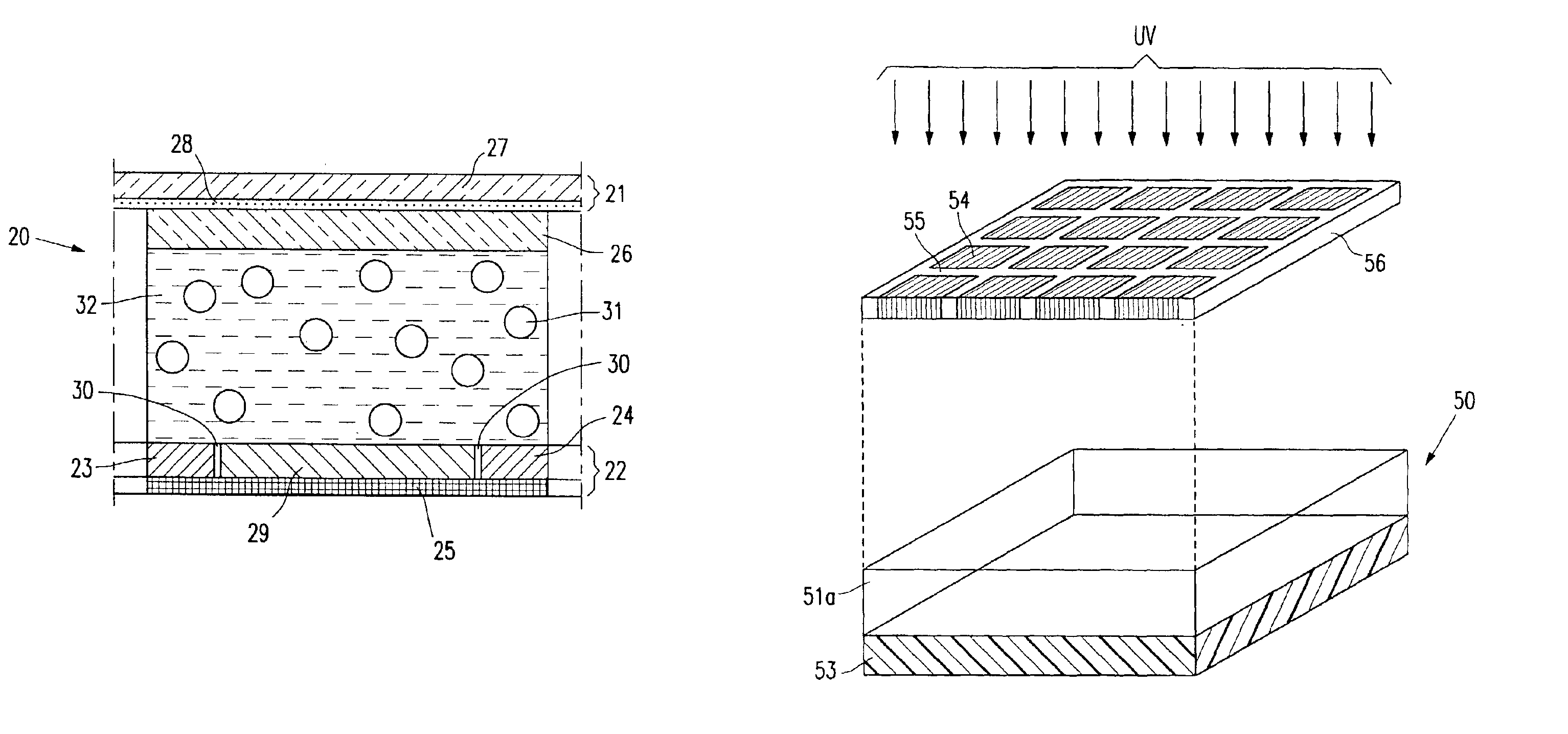
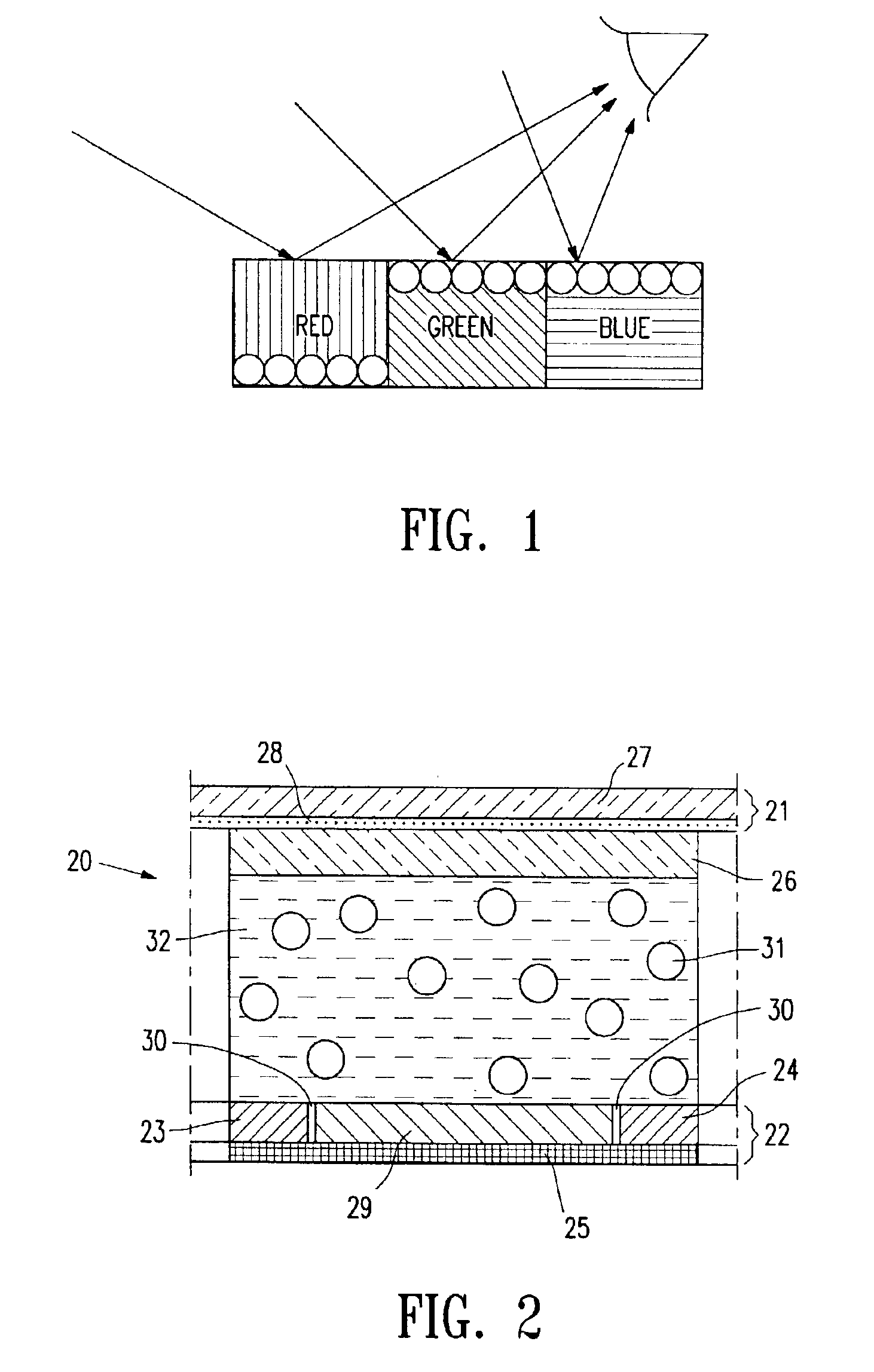
[0024]The EPD of FIG. 1 has conventional top / bottom electrode switching mode. The cells are filled with a suspension in which white charged particles are dispersed in a colored (red, green and blue) dielectric solvent. All three cells in FIG. 1 are shown charged with a voltage difference between the top and bottom electrodes (not shown). In the green and blue cells, ...


PUM

PropertyMeasurementUnit
depthaaaaaaaaaa
depthaaaaaaaaaa
mean particle sizeaaaaaaaaaa

Abstract

The present invention relates to an improved EPD which comprises the in plane switching mode. More specifically, the EPD of the present invention comprises isolated cells formed from microcups of well defined size, shape and aspect ratio and the movement of the particles in the cells is controlled by the in-plane switching mode. The EPD of the present invention may be produced in a continuous manufacturing process, and the display gives improved color saturation.

Description

[0001]This application is a continuation-in-parts of U.S. application Ser. No. 09 / 518,488, filed Mar. 3, 2000. This application also claims the benefit of provisional application 60 / 306,312, filed Jul. 17, 2001.BACKGROUND[0002]The electrophoretic display (EPD) is a non-emissive device based on the electrophoresis phenomenon influencing charged pigment particles suspended in a colored dielectric solvent. This general type of display was first proposed in 1969. An EPD typically comprises a pair of opposed, spaced-apart plate-like electrodes, with spacers predetermining a certain distance between the electrodes. At least one of the electrodes, typically on the viewing side, is transparent. For the passive type of EPDs, row and column electrodes on the top (the viewing side) and bottom plates respectively are needed to drive the displays. In contrast, an array of thin film transistors (TFT) on the bottom plate and a common, non-patterned transparent conductor plate on the top viewing su...

Claims


Application Information

Patent Timeline
Patent Type & Authority Patents(United States)
IPC IPC(8): G02F1/01G02F1/167G02F1/13G02F1/1343G02F1/1679
CPCG02F1/167G02F1/134363G02F2201/12G02F1/1679
Inventor LIANG, RONG-CHANGCHUNG, JERRYCHEN, DAVID
Owner E INK CALIFORNIA
Why Eureka
Try Eureka