Cooling system for motor and cooling control method

Inactive Publication Date: 2005-05-10
HITACHI LTD
View PDF4 Cites 23 Cited by
  • Summary
  • Abstract
  • Description
  • Claims
  • Application Information

AI Technical Summary

Benefits of technology

[0016]An object of the present invention is to provide a cooling system for a motor and a cooling control method which is able to pr

Problems solved by technology

During the operation (power supply control), in the driving motor, a loss due to the flow of a current through a coil or a mechanical loss during high-speed rotation is caused; and, also, in the power converter, a loss is caused during power supply to a semiconductor element for power conversion control or at the time of switching.
Such generation of heat causes a temperature rise of the driving motor and power converter; and, when it is left as it is, the driving motor and power converter cannot exhibit a predetermined performance due to the temperature rise.
Furthermore, the insulating material is reduced in withstand voltage and is finally destroyed, so that the generated heat must be

Method used


Image

  • Cooling system for motor and cooling control method
  • Cooling system for motor and cooling control method
  • Cooling system for motor and cooling control method

Examples


second embodiment

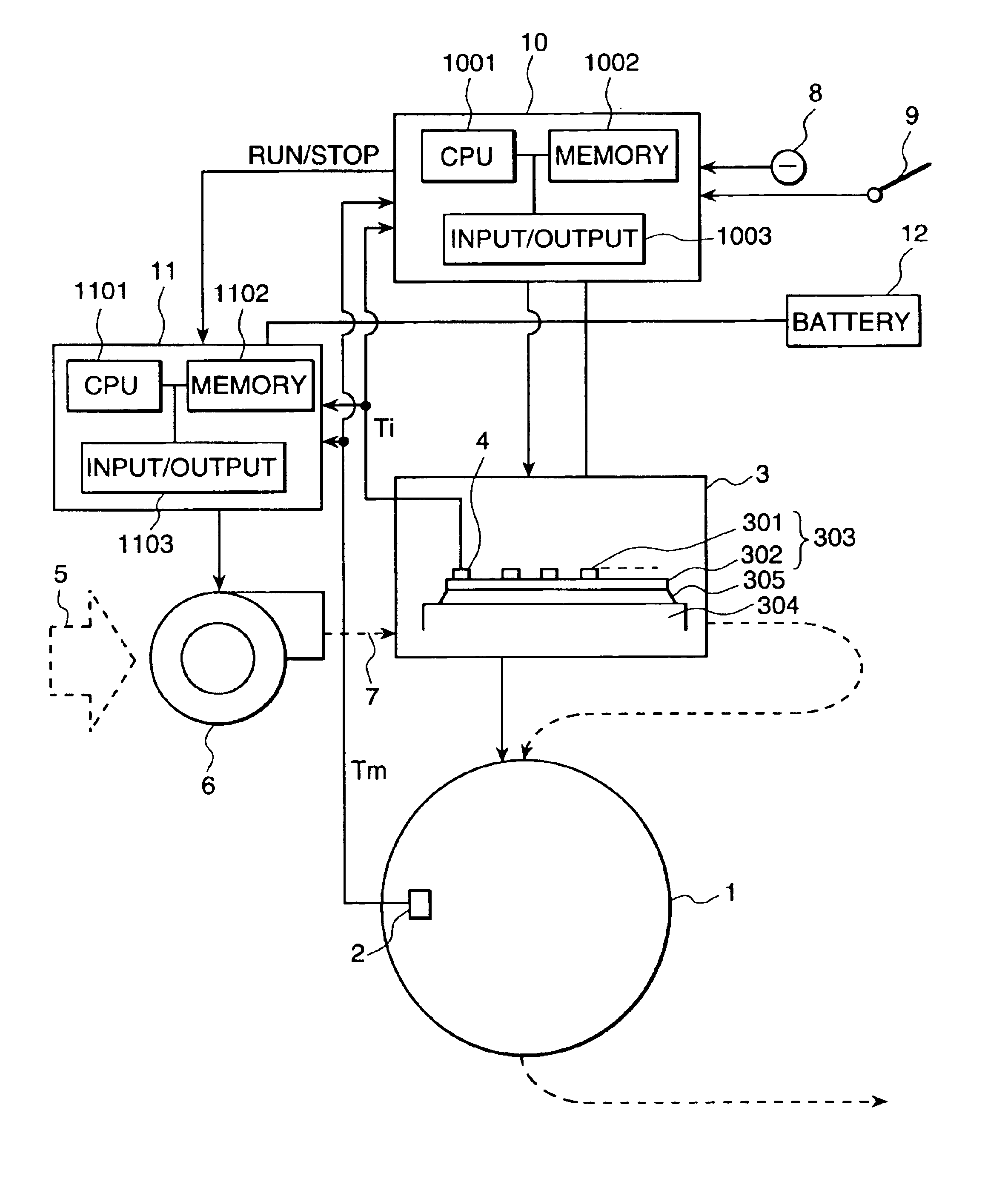
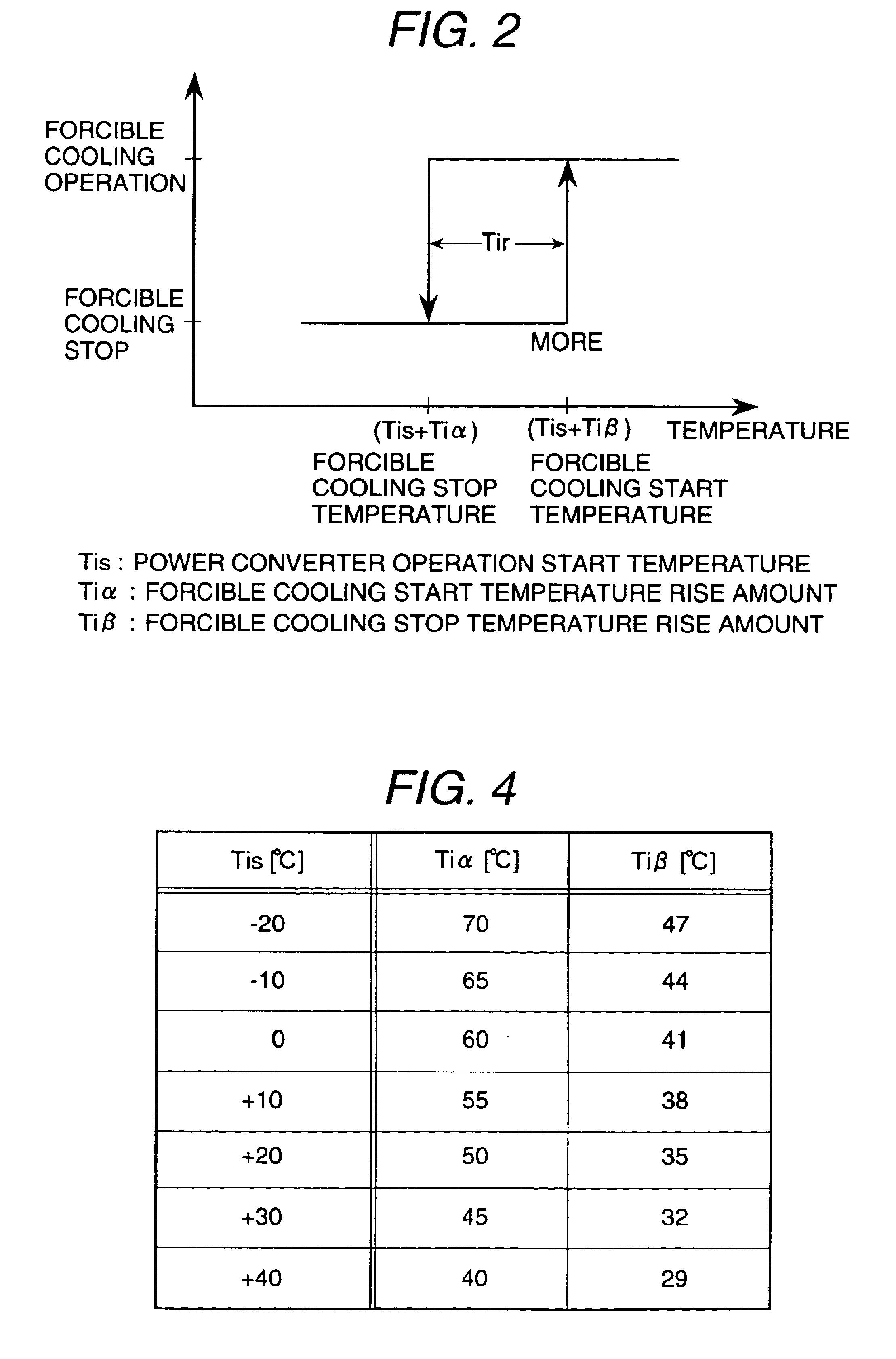
[0085]More specifically, in the control provided in the second embodiment, a process is added to obtain and set the power converter cooling start temperature (Tis+Tiα) and the power converter cooling stop temperature (Tis+Tiβ) at Step S3, in which the CPU 1101 of the cooling control unit 11 selects the cooling start temperature rise amount Tiα and the cooling stop temperature rise amount Tiβ to be added to the power converter operation start temperature Tis according to the power converter operation start temperature Tis.

[0086]A third embodiment of the present invention will be explained with reference to FIGS. 1 to 5. FIG. 5 is a temperature characteristic diagram showing changes with time of the temperature of the power converter of the third embodiment.

[0087]During the stop period, after the end of operation, the temperatures of the driving motor 1 and the power converter 3 slowly lower due to natural cooling. Therefore, when the operation is restarted within a short period after...

third embodiment

[0092]Therefore, the third embodiment is structured so that, in a case of operation restart after such an operation stop for a short time, the temperature of the power converter 3 lowers sufficiently and the power converter operation start temperature Tis1 at the time of the preceding operation start, which is an operation start after a long stop period causing the thermal stress to disappear, is adopted as the power converter operation start temperature Tis for setting the power converter cooling start temperature (Tis+Tiα) and the power converter cooling stop temperature (Tis+Tiα) to be used for forced cooling control of the power converter 3.

[0093]To realize this forced cooling control, the CPU 1101 of the forced cooling control unit 11 of the third embodiment has a clock function, and the memory 1102 has an information holding function for storing and holding a desired stop period which has been preset in consideration of the time necessary for sufficient lowering of the tempera...

fourth embodiment

[0097]The fourth embodiment has a structure such that the heat of the power converter 3 and the driving motor 1 is carried away by a liquid refrigerant, and the heat of the liquid refrigerant is radiated to fresh air by a radiator cooled with a fan. The heat radiation capacity (operation and stop of the motor fan) of the radiator, that is cooled with a fan by fresh air is, controlled. Namely, in a state in which a liquid refrigerant is circulated and the units are force cooled, when the temperature difference between the liquid refrigerant and the fresh air is large, heat is radiated by natural ventilation because the radiation capacity of the radiator is large; and, when the temperature difference between the liquid refrigerant and fresh air is small, heat radiation is promoted by forced ventilation because the radiation capacity of the radiator is small.

[0098]In the fourth embodiment, as a refrigerant circulation system for circulating a refrigerant, a forced cooling refrigerant f...


PUM


Abstract

A cooling system for a motor is prevented from exhibiting a thermal fatigue failure due to a temperature cycle. The operation or stopping of the cooling motor fan 6 of the forced cooling system is controlled using the difference between the temperature thereof and the operation start temperature Tis of the power converter 3. Thus expansion of the temperature range is suppressed.

Description

BACKGROUND OF THE INVENTION[0001]The present invention relates to a cooling system for a motor and to a cooling control method.[0002]An electric vehicle, including a hybrid vehicle, has a system in which power is supplied to a driving motor from a battery via a power converter, and a forced cooling means is provided for suppressing a temperature rise of the power converter and driving motor due to heat generated in correspondence with the operations of the power converter and driving motor.[0003]The forced cooling means is structured so as to force feed a refrigerant, such as fresh air or a cooling liquid (an antifreezing solution), to the power converter and driving motor when the temperatures of the power converter and driving motor rise up to a predetermined cooling start temperature, thereby force cooling them.[0004]For example, a patent document 1 (Japanese Application Patent Laid-open Publication No. Hei 07-213091) and a patent document 2 (Japanese Application Patent Laid-open...

Claims


Application Information

Patent Timeline
IPC IPC(8): F01P3/20H02K9/04H02K9/19F01P3/12F01P1/06F01P3/00F01P1/00B60L3/00H05K7/20H02K9/02H02M7/48
CPCF01P3/20H02K9/19H02K9/04F01P1/06F01P3/12F01P2050/24F01P2050/30F01P2025/46
Inventor SASAKI, KANAMEDOI, HIROAKIHAMADA, HARUKIHAYASHI, MASAAKISAITO, RYUICHI
Owner HITACHI LTD
Why Eureka
Try Eureka