Solid electrolytic capacitor and method for producing the same

a technology of electrolytic capacitor and solid electrolytic capacitor, which is applied in the manufacture of electrolytic capacitors, capacitor electrodes, electrolytic capacitors, etc., can solve the problems of increasing production costs, and affecting the stability of the capacitor so as to achieve stability and stability. stability over a long period of tim

Inactive Publication Date: 2005-05-10
MURATA MFG CO LTD
View PDF16 Cites 41 Cited by
  • Summary
  • Abstract
  • Description
  • Claims
  • Application Information

AI Technical Summary

Benefits of technology

[0012]Accordingly, an object of the present invention is to provide a solid electrolytic capacitor having a masking structure that in forming a solid electrolyte layer on a valve-acting metal substrate having thereon a dielectric film, in which a portion of metal substrate where the solid electrolyte layer is not provided (anode part) can be insulated without fail from the solid electrolyte layer or an electrically conducting layer formed on the solid electrolyte layer using an electrically conducting paste or the like (cathode part) and an its production method.
[0013]Another object of the present invention is to provide a method for coating a masking agent that can efficiently perform masking capable of insulating without fail the anode part from the cathode part of a solid electrolytic capacitor and an apparatus therefor.SUMMARY OF THE INVENTION
[0015]Also, the present inventors have made extensive investigations on the matter that upon electrochemical formation treatment, the electrochemical formation liquid infiltrates into the substrate to increase the leakage current at the time of electrochemical formation so that short circuit to the electrode occurs. As a result, it has been confirmed that dividing the masking step into two stages and applying a temporary masking (first masking layer), performing electrochemical formation treatment based on the position of the temporary masking and applying main masking (second masking layer) on different portions of the substrate so that necessary portions (portions except for the anode part of the solid electrolytic capacitor) can be formed without fail and easily, causing no infiltration of the electrochemical formation liquid across the temporary masking layer.
[0021]Methods (1) and (2) can apply the masking agent within a short period of time, but involve difficulty in maintaining stable work over a long period of time, because of partial solidification on, for example, a bamboo skewer. Further, since the surface of a typical porous formed aluminum foil repels the masking agent, linear application of the masking agent is difficult, and thus the applied masking agent tends to become nonuniform. The screen printing method described in (3) can uniformly apply the masking agent to the foil surface, but involves difficulty in applying the masking agent to a predetermined thickness (about 10-30 μm / one surface) and in applying the masking agent reliably to side surfaces of the formed foil.
[0033][2] A method for producing a solid electrolytic capacitor comprising a metal material having thereon a dielectric film and a solid electrolyte formed on a desired position of the dielectric film, the metal material having valve action, wherein the method comprises the step of coating a masking material solution that infiltrates into the dielectric film and forms a masking layer on the infiltrated portion, wherein a masking resin that has infiltrated into the dielectric film and solidified during the coating step prevents infiltration of a solid electrolyte formed in a subsequent step.
[0052][15] A solid electrolytic capacitor comprising a metal material having thereon a dielectric film and a solid electrolyte formed on a desired position of the dielectric film, the metal material having valve action, wherein said solid electrolytic capacitor comprises a structure in which a masking material solution has infiltrated into said dielectric film and forms a masking layer on the infiltrated portion of the dielectric film, so that the solid electrolyte is prevented from infiltrating into the dielectric film where the masking material solution has infiltrated and masked by the masking layer formed on the infiltrated portion.

Problems solved by technology

The method of using phenol resins or epoxy resins as the masking material (JP-A-3-95910) is disadvantageous in that the capacitor is greatly damaged when pressed by-external force, because the elastic modulus of resin is high and the stress against strains is high.
The method of forming a polyimide film by electro-deposition (JP-A-5-47611) may successfully form a film even inside the pore parts as compared with ordinary coating methods, however, the production cost increases because of necessity of the electrodeposition step and moreover, a dehydration step at a high temperature is necessary so as to form the polyimide film.
The method of forming an insulating resin-made tape or resin coating film part so as to prevent the solid electrolyte from climbing up at the manufacturing (JP-A-5-166681) has difficulty in firmly fixing the tape (film) at edge parts of the substrate and bears a risk of polymer solid electrolyte as the solid electrolyte invading the anode side.
As described above, the conventional masking means are insufficient and actually it has not been clear yet what is like the form (structure) of a masking that can insulate without fail the anode part from the cathode part of a solid electrolytic capacitor.

Method used


Image

  • Solid electrolytic capacitor and method for producing the same
  • Solid electrolytic capacitor and method for producing the same
  • Solid electrolytic capacitor and method for producing the same

Examples


example 1

Masking Step

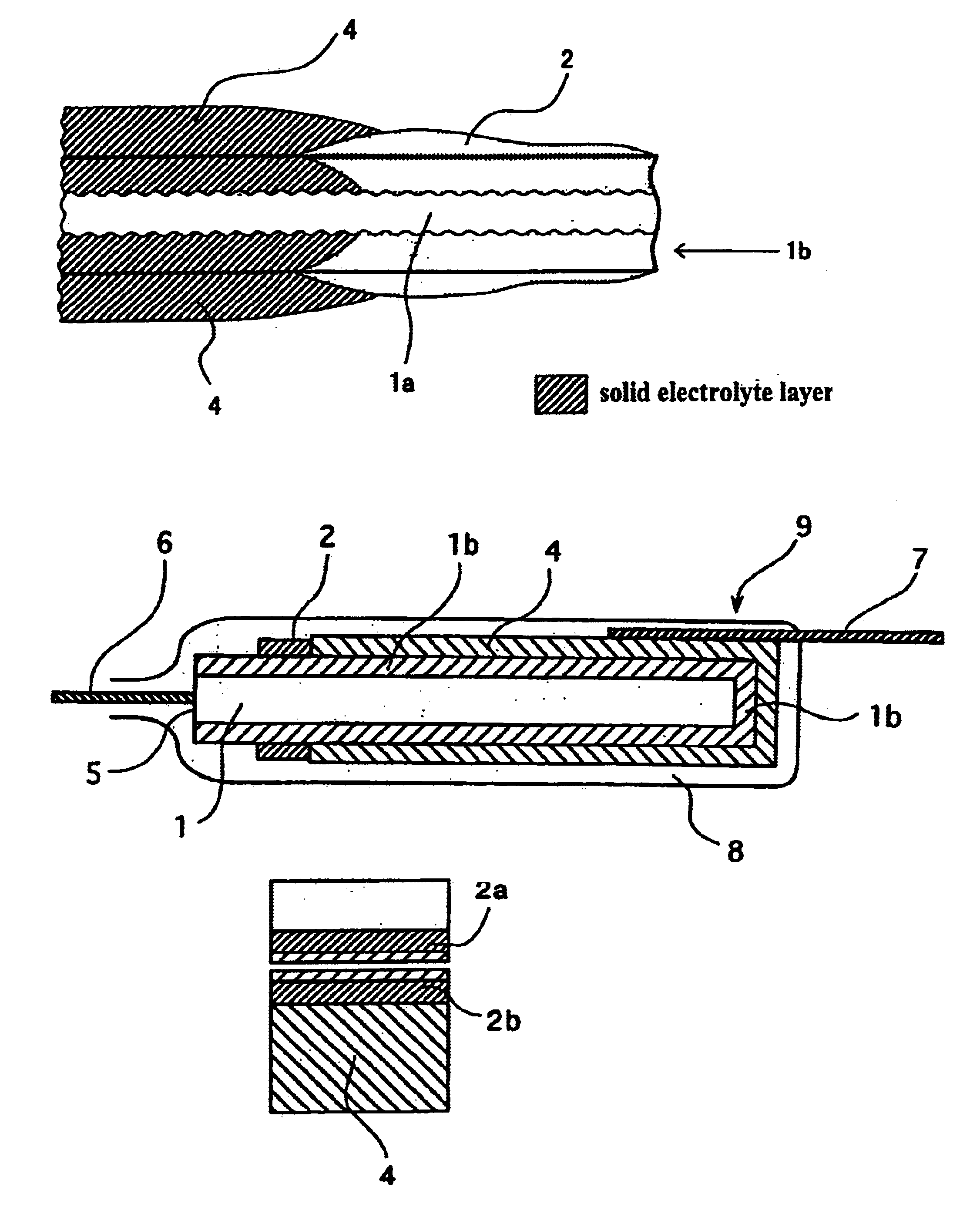
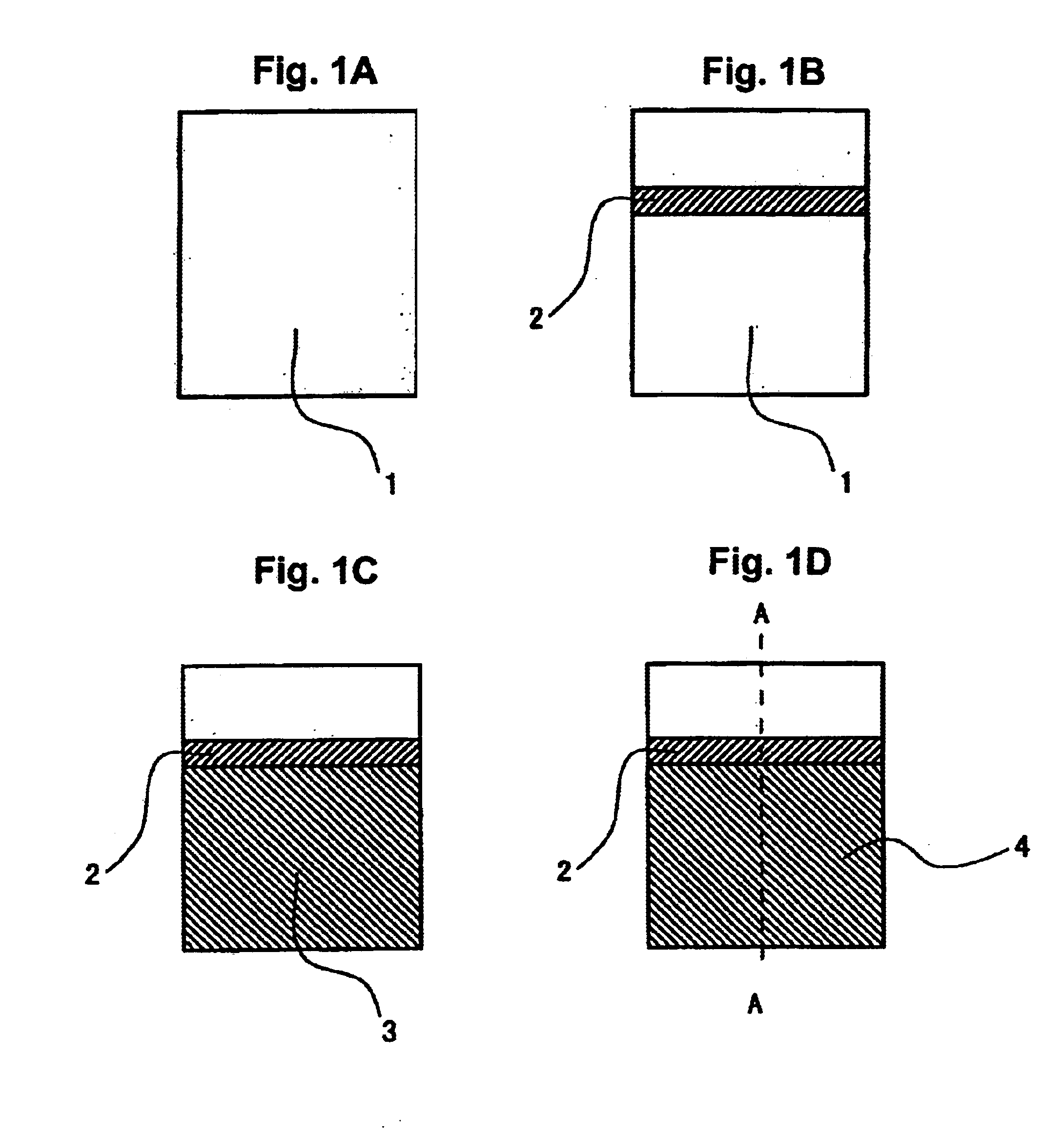
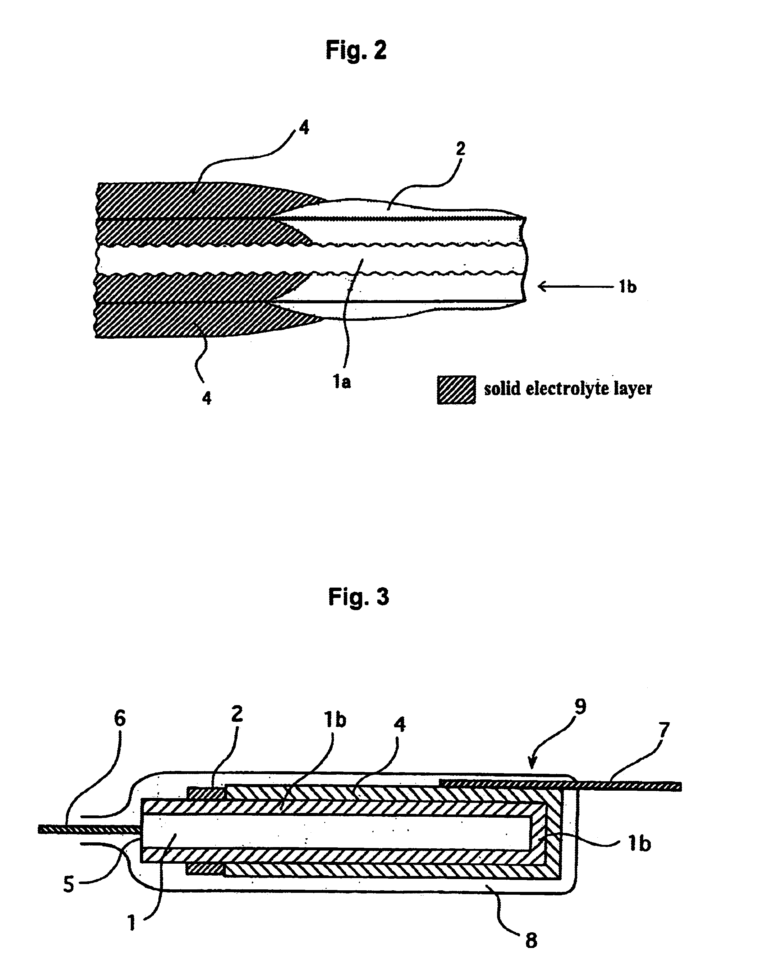
[0129]A 100 μm-thick formed aluminum foil cut (slit) into a width of 3 mm was cut into strips each having a length of 13 mm. One short side part of a foil strip was fixed to a metal-made guide by welding. A polyimide resin solution (UPICOAT™ FS-100L, produced by Ube Industries, Ltd.) adjusted to a viscosity of 800 cp was supplied to a disk-like coating apparatus having a 0.4 mm-width coating surface and while press-contacting the coating surface of the coating apparatus onto the aluminum formed foil, a 0.8 mm-width line was drawn by the solution on the portion 7 mm inside from the unfixed end. The solution was then dried at about 180° C. to form a masking layer (polyimide film).

Electrochemical Forming Step

[0130]The aluminum foil fixed to a metal-made guide was disengaged from the coating apparatus. Thereafter, the area from the distal end to the masking line of the aluminum foil was dipped in an aqueous ammonium adipate solution and a voltage of 13 V was applied to elect...

example 2

[0141]Chip-type solid electrolytic capacitors were manufactured in the same manner as in Example 1 except for using a polyimide resin solution (RIKACOAT™, produced by Shin Nippon Rika K. K.) as the masking material. The measurement of leakage current and the reflow soldering test were also performed in the same manner. The results obtained are shown in Table 1.

example 3

[0142]Chip-type solid electrolytic capacitors were manufactured in the same manner as in Example 1 except that the oxidative polymerization in the step of forming a solid electrolyte was performed by dipping the aluminum foil in an aqueous solution prepared by further adding sodium 2-anthraquinonesulfonate (produced by Tokyo Chemical Industry Co.) to Solution 2 to have a concentration of 0.07 wt %. The measurement of leakage current and the reflow soldering test were also performed in the same manner. The results obtained are shown in Table 1.


PUM

PropertyMeasurementUnit
thicknessaaaaaaaaaa
thicknessaaaaaaaaaa
lengthaaaaaaaaaa

Abstract

The present invention relates to a solid electrolytic capacitor having a masking structure in which the insulation between the anode part and the cathode part can be ensured without fail, to its production method, to a method for coating a masking agent on a solid electrolytic capacitor substrate, and to an apparatus therefor. According to the present invention, the masking material covers the dielectric film on the metal material having valve action and sufficiently infiltrates into the core metal made of a metal having valve action while the solid electrolyte is masked by the masking material without fail, so that a solid electrolytic capacitor can be produced that has a reduced leakage current and a reduced stress generated at the reflow treatment or the like.

Description

CROSS-REFERENCE TO RELATED APPLICATIONS[0001]This application is based on the provisions of 35 U.S.C. Article 111(a) with claiming the benefit of filing dates of U.S. provisional applications Ser. Nos. 60 / 135,843 and 60 / 135,844 filed on May 24, 1999 under the provisions of 35 U.S.C. 111(b), pursuant to 35 U.S.C. Article 119(e) (1).TECHNICAL FIELD[0002]The present invention relates to a solid electrolytic capacitor and to its production method. More specifically, the present invention relates to a solid electrolytic capacitor having a masking structure that in forming a solid electrolyte layer on a valve-acting metal substrate having thereon a dielectric film, in which a portion of metal substrate where the solid electrolyte layer is not provided (anode part) can be insulated without fail from the solid electrolyte layer or an electrically conducting layer formed on the solid electrolyte layer using an electrically conducting paste or the like (cathode part) and to its production met...

Claims


Application Information

Patent Timeline
Patent Type & Authority Patents(United States)
IPC IPC(8): H01G9/00H01G9/04H01G9/15
CPCH01G9/0029H01G9/04H01G9/15H01G11/56Y10T29/413Y02E60/13Y10T29/417
Inventor SAKAI, ATSUSHIMONDEN, RYUJINITOH, HIROSHIOKABE, TOSHIHIROFURUTA, YUJIOHATA, HIDEKISHIRANE, KORO
Owner MURATA MFG CO LTD
Why Eureka
Try Eureka