Light-weight high-power electrical machine

a high-power, electrical machine technology, applied in the direction of electric energy management, magnetic circuit shape/form/construction, electric devices, etc., can solve the problems of low power capability, heavy weight, low efficiency, etc., and achieve the highest energy per, the effect of storing significant energy per weight and high operating speed

Inactive Publication Date: 2005-05-10
REVOLUTION ELECTRIC MOTOR
View PDF11 Cites 48 Cited by
  • Summary
  • Abstract
  • Description
  • Claims
  • Application Information

AI Technical Summary

Benefits of technology

[0018]The machine has many applications and can be used as a motor, generator or alternator. One such application is for use in energy storage flywheel systems. A large inertia steel rim can store significant energy per weight. A solid disc or cylinder can store the highest energy per weight by allowing the highest operating speed. The stored energy is proportional to the peripheral speed. However, for a given desired rotational speed, a rotor in the form of a rim such as that employed in machines in accordance with this invention stores more energy per weight because most of the weight is near the outer diameter of the rotor. This is an advantage of the machine in applications where the rotational speed is limited, such as for operation on mechanical bearings with long life or for lower motor / generator magnetic losses. In prior art inductor alternator flywheel systems, the magnetic losses become significant well below the maximum stress capability of the flywheel. The lower weight of the electrical machine can extend the life of the mechanical bearings and the air core windings eliminate generation of destabilzng radial or axial forces, which along with the reduced weight, can make use of magnetic bearing support easier.
[0019]Besides use in flywheel systems that are known to operate at very high tip speeds for storing large amounts of energy, the machine is well suited for and has many advantages in use with externally connected equipment. Most equipment in industrial applications do not rotate at the high speeds of flywheel systems and it is therefore preferable to have high power capability at slower speeds while having low weight. In one embodiment, the electrical machine can be used for one or more functions in hybrid or electrically driven vehicles. The machine can be mechanically coupled to an engine for producing electric power. It can be used in a flywheel system for storing energy on the vehicle, and it can be used to provide motive force for the vehicle by connection with one or more wheels. The low weight of the rotor and the high power-to-weight capability of the motor makes it particularly suitable as a motor for mounting in or adjacent to the wheels of a hybrid electric vehicle for driving each wheel individually.
[0020]The low cost construction, high efficiency and controllable attributes of the machine also make it well suited for use in alternative energy generation. In one embodiment, the electrical machine is coupled to a wind blade for use in a wind turbine electric generator. The machine is used as an alternator and converts wind energy to electricity. The field coil allows the output to be controlled despite variations in the wind speed and the light weight makes support of the electrical machine easier.
[0021]A further use of the machine is in continuous power systems. The electrical machine serves as a flywheel that is coupled to an engine through a clutch. The rotor is normally rotated by utility power through use of a synchronous inverter. When utility power fails, the rotor continues to rotate due to its rotational inertia and it provides power. If the interruption is extended, the engine is started, the clutch is engaged and the engine rotates the rotor to provide continuous power. Because engines typically rotate at relatively slow speeds, the machine provides continuous power with lower weight and with a potentially longer bearing life.

Problems solved by technology

Brushless rotary electrical machines such as motors, generators and alternators have typically suffered from one or more of the following deficiencies, low power capability, heavy weight, low efficiency, complex and costly construction, cogging, and required use of expensive and complex cooperating electronics.
Unfortunately, this construction is complicated and the use of many rare earth magnets and low loss magnetic conducting bars is expensive.
Besides the expense of the electrical machine itself the associated electronics to drive the electrical machine are also expensive.
These electronics can be prohibitively expensive for use of the electrical machine in many applications and the life of these electronics can be limiting.
Although such electrical machines can reduce the cost of associated electronics for operation, they are heavy and have provided only a very low ratio of power capability to weight.

Method used


Image

  • Light-weight high-power electrical machine
  • Light-weight high-power electrical machine
  • Light-weight high-power electrical machine

Examples


Embodiment Construction

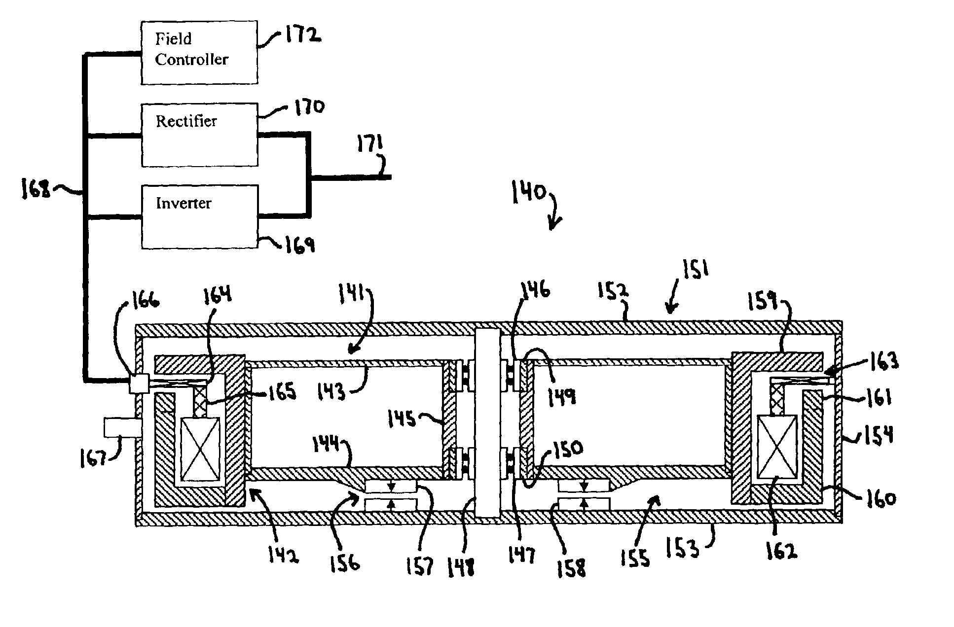
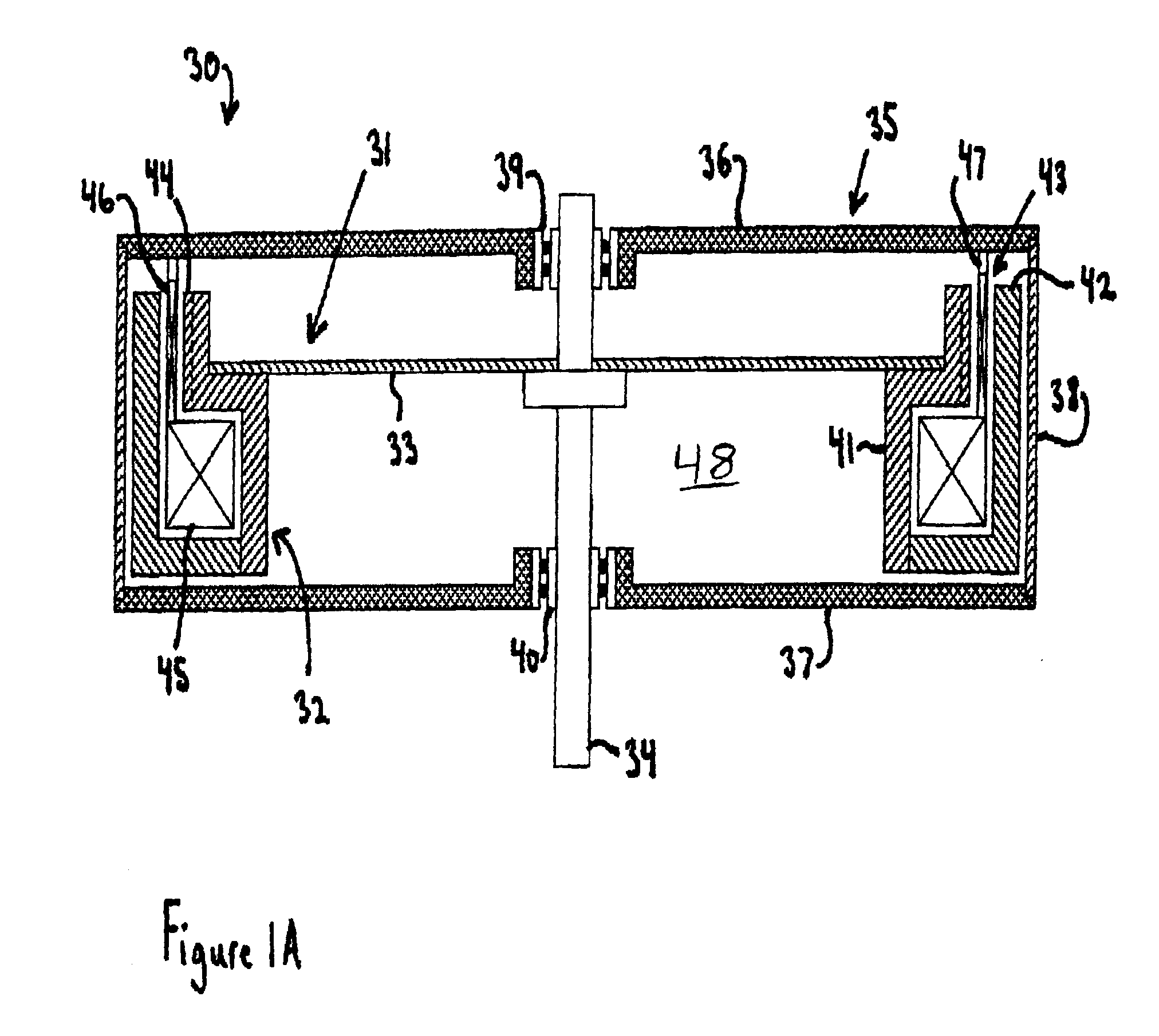
[0037]Turning to the drawings wherein like characters designate identical or corresponding parts, and more particularly to FIG. 1A, a light weight high power electrical machine 30 in accordance with the invention is shown having a rotor 31 with a rim 32 and a center hub 33. The rotor 31 has a substantially open center portion 48, within the inner diameter of the rotor, except for the hub, to minimize the weight of the electrical machine 30 and maximize the moment of inertia of the rotor 32 about its axis of rotation. This allows the diameter of the rim 32 where force is generated to be made large for maximizing both the torque and power capability of the electrical machine 30. Thus, the power capability of the electrical machine is maximized by having force generation occur at the largest diameter. The open center portion 48 within the rim 32 could be used for other elements used in the application, such as electronic components, a brake or clutch, etc.

[0038]The center hub portion 3...


PUM


Abstract

A brushless electrical machine, usable as a motor, generator, or alternator, has a rotor that is comprised of a rim portion and a substantially open center portion. The rim portion has a partially hollow core in which a stationary field coil is supported. Current to the field coil generates magnetic flux that circulates in a poloidal flux path in the rim, crossing a single magnetic air gap formed by the rim. Protrusions in the rim located around the circumference form poles all having the same polarity. As the rotor rotates, the flux exiting the poles passes through multiple stationary armature windings around the circumference that are located in the single air gap. An AC voltage is induced in the armature windings from rotation.

Description

[0001]This is related to the following U.S. applications:[0002]Provisional Application No. 60 / 340,158 filed on Dec. 15, 2001, entitled “Light Weight High Power Electrical Machine”,[0003]patent application Ser. No. 10 / 017,167 filed on Dec. 15, 2001, and entitled “Homopolar Hybrid Electric Machine”,[0004]Provisional Application No. 60 / 394,374 filed on Jul. 8, 2002, and entitled “Compact Heteropolar Hybrid Alternator-Motor”,[0005]Provisional Application No. 60 / 358,110 filed on Feb. 19, 2002, and entitled “Airgap Armature for Inductor Alternator Machine”, and patent application Ser. No. 10 / 224,802 filed on Aug. 21, 2002, and entitled “Airgap Armature”,[0006]Provisional Application No. 60 / 385,324 filed on Jun. 3, 2002 and entitled “High Performance Axial Gap Alternator Motor”, and[0007]Provisional Application No. 60 / 340,157 filed on Dec. 15, 2001, and entitled “Hybrid Vehicle Power System”, and 60 / 382,802 filed on May 23, 2002, and entitled “Parallel Hybrid Electric Vehicle”,[0008]Provis...

Claims


Application Information

Patent Timeline
Patent Type & Authority Patents(United States)
IPC IPC(8): F16C39/00F16C39/06H02K19/10H02K19/02H02K19/06H02K29/06H02K7/09H02K9/06H02K29/08H02K7/02H02K7/00H02K3/46H02K9/04H02K3/47
CPCF16C39/063H02K11/048H02K19/06H02K19/103H02K3/47H02K7/025H02K7/09H02K29/08H02K9/06B60L7/14B60L15/20B60L15/2009B60L2210/40B60L2220/14B60L2240/421B60L2240/423B60L2260/26B60L2220/50B60L50/61B60L50/30Y02T10/62Y02T10/64Y02T10/72Y02T10/70Y02T10/7072H02M7/00
Inventor GABRYS, CHRISTOPHER W.
Owner REVOLUTION ELECTRIC MOTOR
Why Eureka
Try Eureka