Method and system for controlling the operation of a hydrogen generator and a fuel cell

a technology of hydrogen generator and fuel cell, which is applied in the direction of secondary cell charging/discharging, electric vehicles, fuel cells, etc., can solve the problems of overheating scenario, process is inherently slow for larger reformers with significant thermal mass, and reduce the hydrogen production ra

Inactive Publication Date: 2005-05-17
CELLEX POWER PRODS
View PDF6 Cites 69 Cited by
  • Summary
  • Abstract
  • Description
  • Claims
  • Application Information

AI Technical Summary

Benefits of technology

[0022]The method may further comprise generating a hydrogen consumption control command based on a comparison of the measured pressure of the hydrogen within the flow path and pset. The hydrogen consumption control command may be delivered directly to the fuel cell for controlling the amount of hydrogen consumed by the fuel cell or to a power converter or fuel cell controller operatively connected to the fuel cell. Preferably the rate of hydrogen consumed by the fuel cell is adjusted at sufficiently frequent intervals to ensure that the pressure of hydrogen in the flow path is maintained between a minimum and a maximum pressure value. For example, the amount of hydrogen consumed by the fuel cell may be adjusted continuously as the measured hydrogen pressure in the flow path differs from pset. One advantage of the invention is that the pressure sensor may comprise a low-cost pressure transducer located in the flow path rather than a mass flow meter.
[0023]The set points pset, iset and mset may be calculated at discrete intervals or may be continuously updated. In one embodiment of the invention the value of pset may depend in part upon the preferred operating temperature of the hydrogen generator. The method may include the step of processing the hydrogen generated by the hydrogen generator to produce a substantially pure hydrogen stream and a hydrogen depleted stream. The hydrogen depleted stream may be diverted to a burner to produce heat useful in regulating the temperature of the hydrogen generator.
[0024]The invention also relates to a system for regulating the current output of a dead-ended hydrogen fuel cell receiving a supply of hydrogen produced by a hydrogen generator. The system includes a hydrogen delivery vessel disposed between the hydrogen generator and the fuel cell for delivering a flow of hydrogen from the hydrogen generator to the fuel cell; a pressure sensor located in the delivery vessel for measuring the pressure of the hydrogen; a first controller receiving input from the pressure sensor, wherein the first controller generates a hydrogen consumption control command; a current sensor for measuring the current produced by the fuel cell; and a second controller receiving input from the current sensor, wherein the second controller generates a fuel supply control command. In accordance with the invention, the first controller is operatively connected to the fuel cell to regulate the amount of hydrogen consumed by the fuel cell and the second controller is operatively connected to the hydrogen generator to regulate the amount of hydrogen produced by the hydrogen generator.
[0025]Preferably the first controller generates the hydrogen consumption control command based on a comparison of the hydrogen pressure measured by the pressure sensor and a target hydrogen pressure pset. In one embodiment the first controller does not receive input from the current sensor.
[0026]In a further embodiment of the invention, the second controller generates the fuel supply control command based on a comparison of the fuel cell current measured by the current sensor and a target fuel cell current iset. In another embodiment the system includes a hydrogen mass flow processor which receives input from the pressure sensor and the current sensor. The processor calculates a target hydrogen mass flow mset corresponding to iset and a hydrogen mass flow estimate {dot over (m)}in according to the following formula: m.i⁢ ⁢n=(VR·T)·ⅆPⅆt+m.out⁢⁢where:⁢ [1]m.out=nc·igross2·F[2]
[0027]where {dot over (m)}in is the estimated mass flow produced by the hydrogen generator and, {dot over (m)}out is the estimated mass flow of hydrogen consumed by the fuel cell, and wherein

Problems solved by technology

This process is inherently slow for larger reformers with significant thermal mass.
One challenge in mating the two technologies is that since there is no path for excess hydrogen to escape, production rates of hydrogen from the hydrogen generator must match the consumption rate of hydrogen in the fuel cell otherwise any imbalance will manifest as pressure fluctuations in the hydrogen feed lines between the generator and the fuel cell.
This will therefore reduce the hydrogen production rate and will also force excess hydrogen rich gas into the reformer oxidation reactor, potentially leading to an overheating scenario.Decreasing pressure: A decrease in hydrogen pressure will potentially negatively affect the output of the fuel cell, since fuel cells typically rely on a specific pressure drop across the stack to ensure optimum reaction rates.
Even in the case where a hydrogen regulator is used to stabilize this pressure, if the pressure drops below a minimum acceptable level, the pressure may be unacceptable for normal fuel cell operation.
This purge briefly and instantaneously requires excess hydrogen from the hydrogen generator which generally cannot be supplied quick enough.
The result is a sudden negative pressure fluctuation.
Because the purge relies on hydrogen pressure to blow out contaminants, a negative pressure fluctuation may seriously decrease the effectiveness of the purge, which may in turn trigger further purging.

Method used


Image

  • Method and system for controlling the operation of a hydrogen generator and a fuel cell
  • Method and system for controlling the operation of a hydrogen generator and a fuel cell
  • Method and system for controlling the operation of a hydrogen generator and a fuel cell

Examples


Embodiment Construction

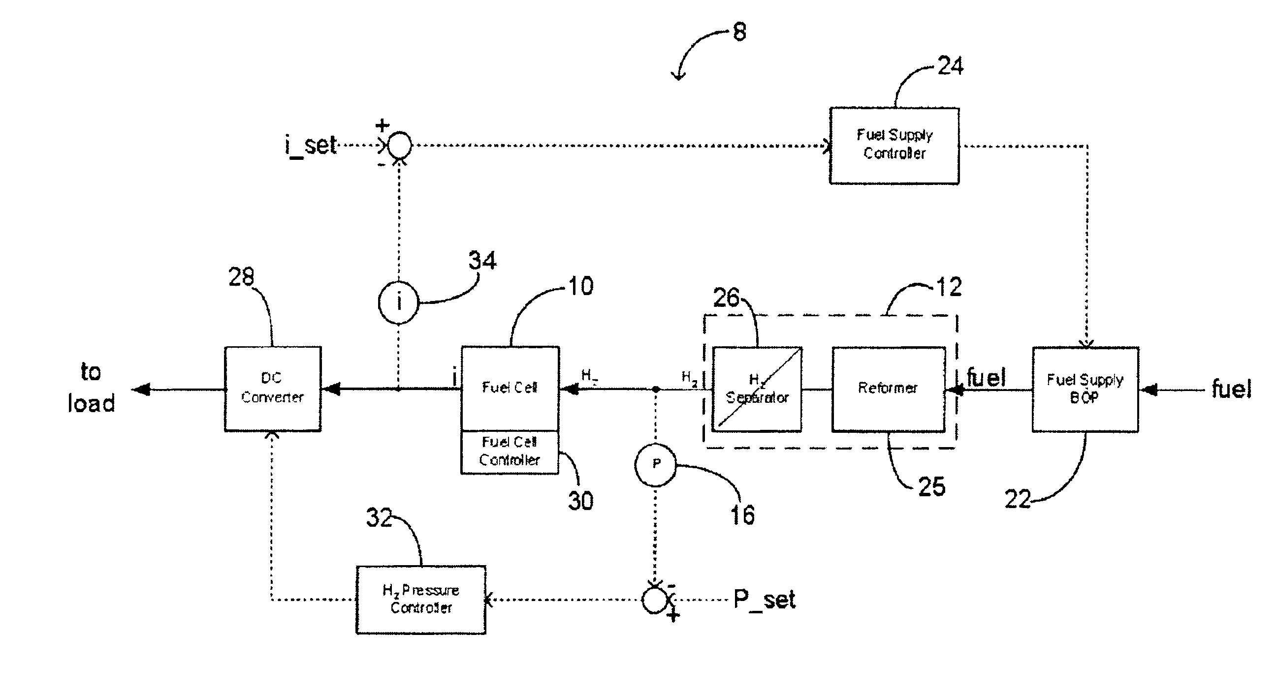
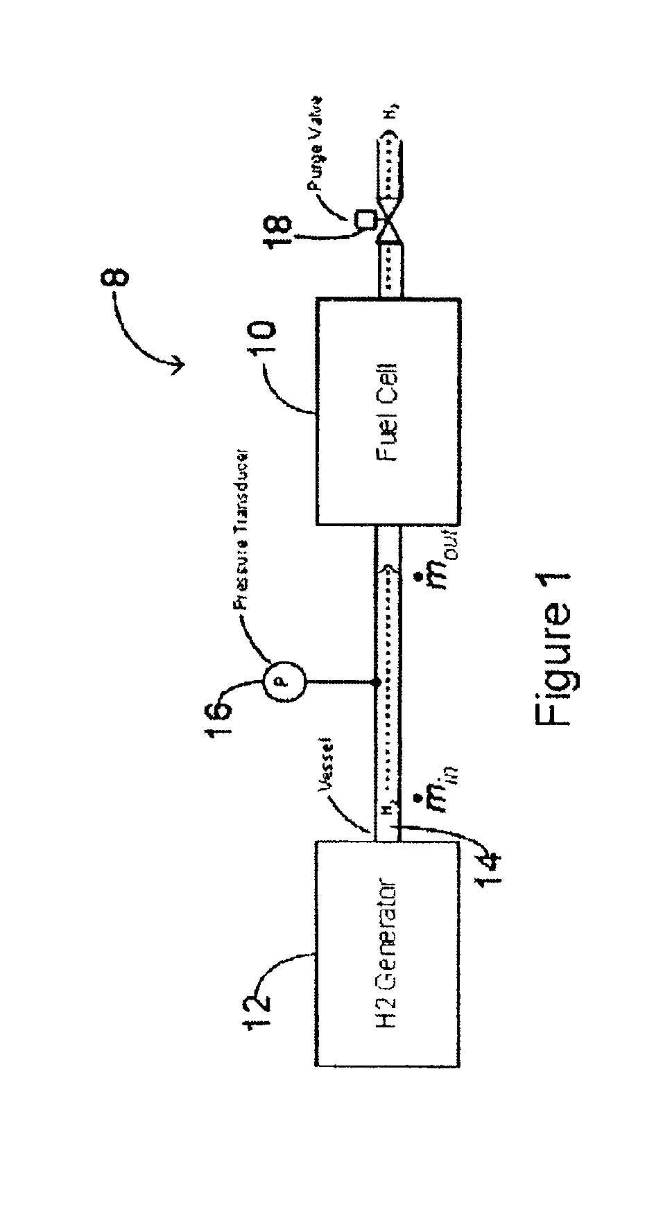
[0047]FIG. 1 illustrates schematically one possible embodiment of the Applicant's control system 8 for regulating the supply of fuel to a fuel cell 10. In the illustrated embodiment fuel cell 10 receives a supply of hydrogen fuel from a hydrogen generator 12 through a supply conduit 14. As described further below, hydrogen generator 12 may comprise, for example, a reformer coupled to a hydrogen separator. A pressure sensor 16 is provided for measuring the hydrogen pressure within conduit 14.

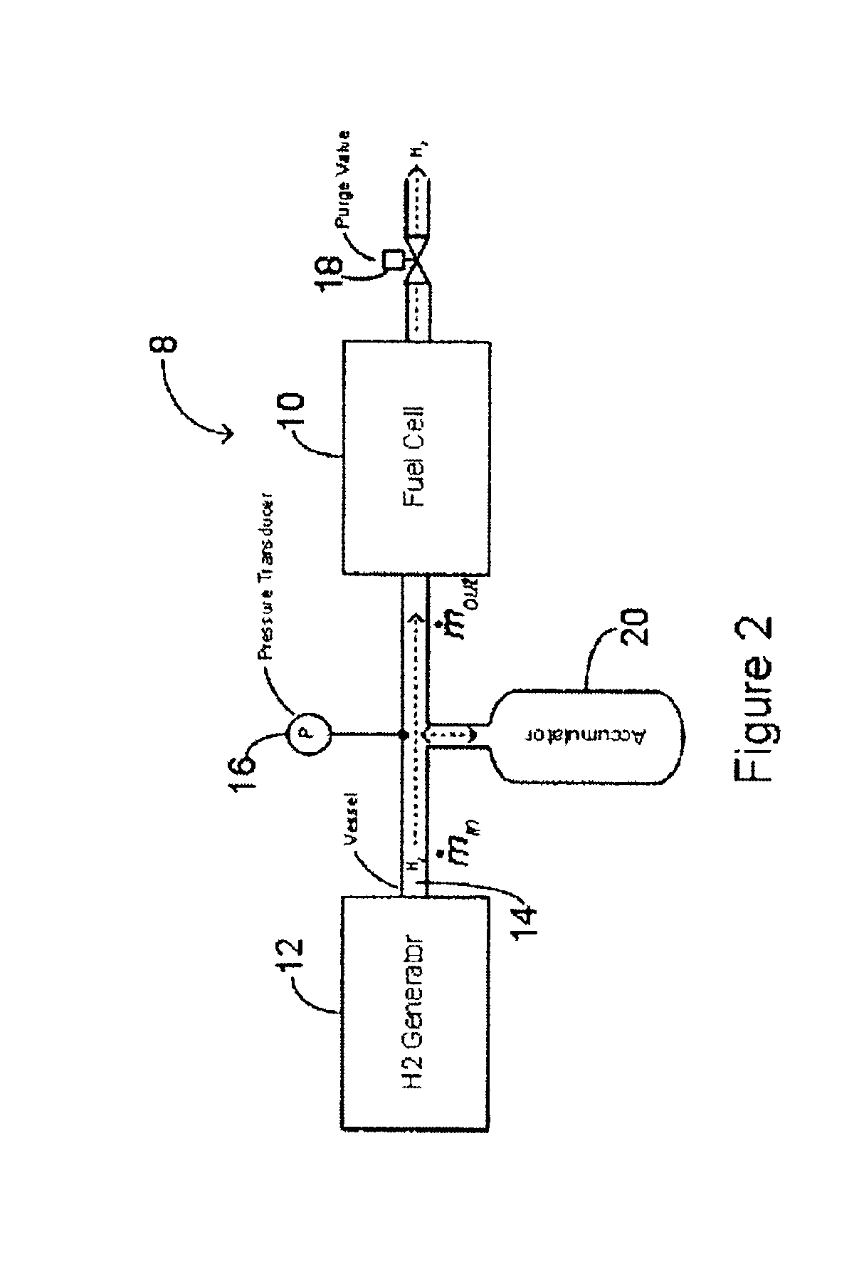
[0048]Hydrogen fuel cells are typically dead-ended. As used in this patent application “dead-ended” means that hydrogen entering fuel cell 10 is consumed and there is ordinarily no path for excess hydrogen to exit directly (this includes systems that recirculate hydrogen). As shown in FIG. 1, a purge valve 18 may be provided for periodically expelling from fuel cell 10 contaminants and water vapour which build in concentration therein. In particular, the purge system temporarily opens the dead-en...


PUM

PropertyMeasurementUnit
currentaaaaaaaaaa
pressureaaaaaaaaaa
mass flow rate msetaaaaaaaaaa

Abstract

This application relates to a method and system for controlling the supply of fuel to a dead-ended hydrogen fuel cell. The invention may be utilized, for example, to more efficiently integrate the operation of a hydrogen fuel cell and a hydrogen generator, such as a reformer coupled with a hydrogen separation unit. The invention ensures that the production and consumption of hydrogen are effectively balanced to avoid negative feed line pressure fluctuations. The fuel supply control subsystem and hydrogen consumption control subsystems are, however, “decoupled” and hence independently operable. The invention may include an accumulator disposed in a flow path between the hydrogen generator and the fuel cell for storing hydrogen under pressure. The accumulator is sufficiently large in volume such that the pressure of hydrogen in the flow path does not deviate substantially from a target pressure, even during the waste purging sessions. The system enables the use of low-cost pressure transducers in place of mass flow meters. In one aspect of the invention raffinate flow from the hydrogen separator can be controllably adjusted to regulate the temperature or other operating parameters of the reformer.

Description

TECHNICAL FIELD[0001]This application relates to a method and system for controlling the supply of fuel to a dead-ended hydrogen fuel cell. The invention may be utilized, for example, to more efficiently integrate the operation of a hydrogen fuel cell and a hydrogen generator, such as a reformer coupled with a hydrogen separation unit.BACKGROUND[0002]Fuel cells generate electrical current by consuming hydrogen and oxygen. Hydrogen fuel may be supplied to the fuel cell from a hydrogen generator, such as a steam reformer coupled with a palladium membrane hydrogen separator. The reformer is provided for producing hydrogen from a conventional fuel such as natural gas, propane or methanol. The reformer and hydrogen separator produces a substantially pure hydrogen stream in response to a given feed rate of methanol (or other fuel). This process is inherently slow for larger reformers with significant thermal mass. In a fuel cell system, this pure hydrogen gas produced by the hydrogen gene...

Claims


Application Information

Patent Timeline
Patent Type & Authority Patents(United States)
IPC IPC(8): H02J7/00H01M8/04H01M8/06
CPCH01M8/04089H01M8/04201H01M8/04231H01M8/04373H01M8/04738H01M8/04753H01M8/04992H01M8/0612H01M8/04589H01M8/04388Y02E60/50H01M8/0662
Inventor LEBOE, DAVID
Owner CELLEX POWER PRODS
Why Eureka
Try Eureka