
Multilayer imageable elements

a technology of imageable elements and multi-layer printing, which is applied in thermography, photosensitive materials, instruments, etc., can solve the problems of time-consuming process and small change in mask dimensions, and achieve the effect of increasing the length of the press run

Inactive Publication Date: 2005-05-17
KODAK POLYCHROME GRAPHICS
View PDF29 Cites 50 Cited by
  • Summary
  • Abstract
  • Description
  • Claims
  • Application Information

AI Technical Summary

Benefits of technology

[0034]The imageable elements are positive working thermally imageable multi-elements that are resistant to the press chemistries used in lithographic printing, especially in printing processes using ultraviolet-curing inks, where rinsing agents with a high content of esters, ethers or ketones are used. In addition, they can be baked to increase press run length.

Problems solved by technology

This is a time-consuming process.
In addition, dimensions of the mask may change slightly due to changes in temperature and humidity.
Thus, the same mask, when used at different times or in different environments, may give different results and could cause registration problems.

Method used


Image

  • Multilayer imageable elements
  • Multilayer imageable elements
  • Multilayer imageable elements

Examples


example 1

[0100]This example illustrates preparation of a functionalized novolac resin.

[0101]N-13 (24 g, 199.75 millimoles) was added in acetone (66 g) with stirring and the resulting mixture cooled 10° C. in an ice / water bath. p-Toluene sulfonyl chloride (20.02 millimoles) at 10° C. over 1 min. Triethylamine (19.63 millimoles) was added at 10° C. over 2 min. The reaction mixture was stirred for 10 min at less than 15° C. Acetic acid (8.33 millimoles) was added at 10° C. over 10 sec, and the reaction mixture stirred for 15 min. Water / ice (160 g), and acetic acid (1.2 g, 20.02 millimoles) was added over several minutes at 15° C. and the reaction mixture stirred below 15° C. for 5 min.

[0102]The supernatant was decanted from the tacky solid that formed in the bottom of the reaction flask. Acetone (354 g) was added, and the reaction mixture stirred until a clear solution was obtained. Water / ice (160 g) and acetic acid (1.2 g, 20.02 millimoles) were added over several minutes and the reaction mixt...

example 2

[0103]This example illustrates preparation of a Copolymer 1, a copolymer having 35 mol % N-phenylmaleimide, 30 mol % methacrylic acid and 35 mol % N-[2-(2-Oxo-1-imidazolidinyl)ethyl]methacrylamide.

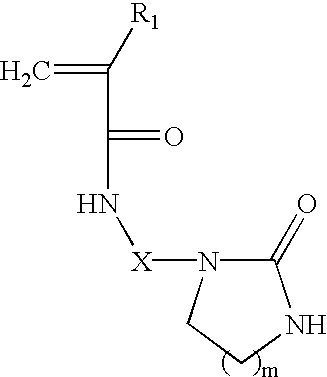
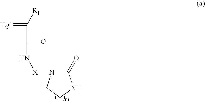
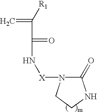
[0104]N-phenylmaleimide (14.58 g), methacrylic acid (1.04 g), N-[2-(2-Oxo-1-imidazolidinyl)ethyl]methacrylamide (24.39 g) (Aldrich, Milwaukee, Wis., USA, contains 30% water, 3% aminoethyl ethylene urea, 25% methacrylic acid and is inhibited with 1800 ppm HQ) and dimethyl formamide (136.01 g) were placed in a 1 L reaction kettle fitted with a reflux condenser, nitrogen supply, thermometer, stirrer, and heating mantle. Nitrogen was bubbled through the reaction mixture for one hour. The reaction was heated to 60° C. under nitrogen and 2,2-azobisisobutyronitrile (AIBN) (0.054 g in 10 g of dimethyl formamide) was added. The reaction mixture was stirred under nitrogen at 60° C. for about 20 hr. The reaction mixture was slowly added to water (about 1 L), and the resulting precipitate filtered. Th...


PUM

PropertyMeasurementUnit
mol %aaaaaaaaaa
wt %aaaaaaaaaa
wt %aaaaaaaaaa

Abstract

Multilayer, positive working, thermally imageable elements are disclosed. The elements produce bakeable lithographic printing plates that are resistant to press chemistries. The elements have a substrate, an underlayer, and a top layer. The underlayer comprises a resin or resins having activated methylol and / or activated alkylated methylol groups, such as a resole resin, and a polymeric material that comprises, in polymerized form, (a) methacrylic acid; (b) N-phenylmaleimide, N-cyclohexylmaleimide, N-benzylmaleimide, or a mixture thereof; and (c) one or more monomers of the structure: in which:R1 is H or methyl; X is —(CH2)n—, where n is an integer from 2 to 12; —(CH2—CH2—O)p—CH2—CH2—, where p is an integer from 1 to 3; or —Si(R′)(R″)— where R′ and R″ are each independently methyl or ethyl; and m is 1, 2, or 3.

Description

FIELD OF THE INVENTION[0003]The invention relates to lithographic printing. In particular, this invention relates to multi-layer, positive-working, thermally imageable elements that are useful in forming lithographic printing plates.BACKGROUND OF THE INVENTION[0004]In conventional or “wet” lithographic printing, ink receptive regions, known as image areas, are generated on a hydrophilic surface. When the surface is moistened with water and ink is applied, the hydrophilic regions retain the water and repel the ink, and the ink receptive regions accept the ink and repel the water. The ink is transferred to the surface of a material upon which the image is to be reproduced. Typically, the ink is first transferred to an intermediate blanket, which in turn transfers the ink to the surface of the material upon which the image is to be reproduced.[0005]Imageable elements useful as lithographic printing plate precursors typically comprise an imageable layer applied over the hydrophilic surf...

Claims


Application Information

Patent Timeline
Patent Type & Authority Patents(United States)
IPC IPC(8): B41M5/36B41C1/10G03F7/004G03F7/00G03F7/26
CPCB41C1/1016Y10S430/165Y10S430/111B41C2210/02B41C2210/262B41C2210/14B41C2210/22B41C2210/24B41C2210/06
Inventor KITSON, PAULRAY, KEVIN B.JAREK, MATHIASPAPPAS, S. PETER
Owner KODAK POLYCHROME GRAPHICS
Learn More