Objective lens arrangement for use in a charged particle beam column

a technology of charged particle beam and object, which is applied in the field of inspection/measurement techniques, can solve the problems of reducing the electrostatic field in the vicinity of the sample, impede the collection of secondary electrons, and the approach does not provide sufficient reduction of the chromatic primary beam, so as to reduce the minimal energy of the effectively focusable charge particle beam

Inactive Publication Date: 2005-05-24
APPL MATERIALS ISRAEL LTD
View PDF7 Cites 15 Cited by
  • Summary
  • Abstract
  • Description
  • Claims
  • Application Information

AI Technical Summary

Benefits of technology

[0012]Another problem to be solved is avoidance of the creation of a strong electrostatic field between the lowermost electrode of the lens arrangement (e.g., cap-electrode in a specific configuration) and the tilted sample. To this end, the cap is to be formed with a small opening (about 2 mm), otherwise deflecting and the resolution. The use of a smaller opening impedes the collection of secondary electrons, especially when operating with a so-called “in-lens” or “in-column” detector, and, on the other hand, significantly reduces the electrostatic field in the vicinity of the sample, which might reduce the resolution. The in-lens or in-column detector is typically a plate-like detector formed with an opening surrounded by sensing regions, and is accommodated in the path of a primary beam such that the primary beam propagation axis intersects with said opening, which therefore serves as the primary beam hole.
[0015]Preferably, the either one of upper and lower electrodes or both of them are made of a magnetic material like mu-metal, to shield magnetic disturbance fields. Preferably, at least the lower electrode of the electrostatic lens is conically shaped, and more preferably, both the upper and lower electrodes are conically shaped. This enables to decrease an effective working distance, which is the distance between the sample plane and a plane of the electrode closest to the sample measured along the optical axis of the lens arrangement. The upper electrode may be a multiple-electrode structure, such as dipole, quadruple, or octupole, and may therefore operate as a beam deflector.
[0020]According to yet another aspect of the invention, there is provided a method of focusing a charged particle beam onto a sample while propagating through a charged particle beam column, the method comprising: passing the charged particle beam through an objective lens arrangement having a magnetic lens and an electrostatic lens, wherein the electrostatic lens includes upper and lower electrodes arranged in a spaced-apart coaxial relationship along an optical axis of the lens arrangement; applying a predetermined voltage to said upper electrode to adjust a position of the principal plane of the lens arrangement to provide a desired magnification coefficient and numerical aperture of the lens arrangement. By this, the adjustment of the principal plane optimum resolution can be achieved.
[0022]According to yet another aspect of the invention, there is provided a method of focusing a charged particle beam onto a sample while propagating the through a charged particle beam column, the method comprising accelerating the charged particle beam on its way towards an objective lens arrangement and decelerating the accelerated charged particle beam in the vicinity of the sample, wherein said decelerating comprises passing the charged particle beam through openings in upper and lower electrodes arranged in a spaced-apart coaxial relationship along the beam propagation axis, thereby reducing a minimal energy of the effectively focusable charged particle beam.

Problems solved by technology

Although appropriate regulation of the electrostatic field by a voltage supply to a cap-electrode enables the reduction of chromatic aberration when operating with the normal incidence of the primary beam onto the sample and with the HAR mode (high gradient electric field in the vicinity of the sample, e.g., Vcap=3 kV), this approach does not provide sufficient reduction of chromatic primary beam while operating with a relatively low-gradient electric field in the vicinity of the sample (e.g., zero voltage on the cap-electrode Vcap=0 V).
Another problem to be solved is avoidance of the creation of a strong electrostatic field between the lowermost electrode of the lens arrangement (e.g., cap-electrode in a specific configuration) and the tilted sample.
The use of a smaller opening impedes the collection of secondary electrons, especially when operating with a so-called “in-lens” or “in-column” detector, and, on the other hand, significantly reduces the electrostatic field in the vicinity of the sample, which might reduce the resolution.

Method used


Image

  • Objective lens arrangement for use in a charged particle beam column
  • Objective lens arrangement for use in a charged particle beam column
  • Objective lens arrangement for use in a charged particle beam column

Examples


Embodiment Construction

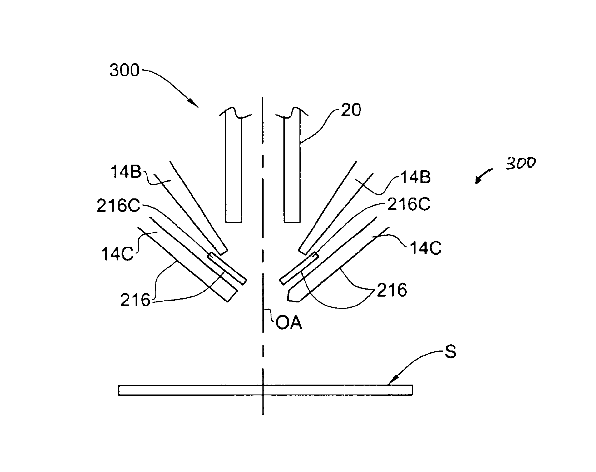
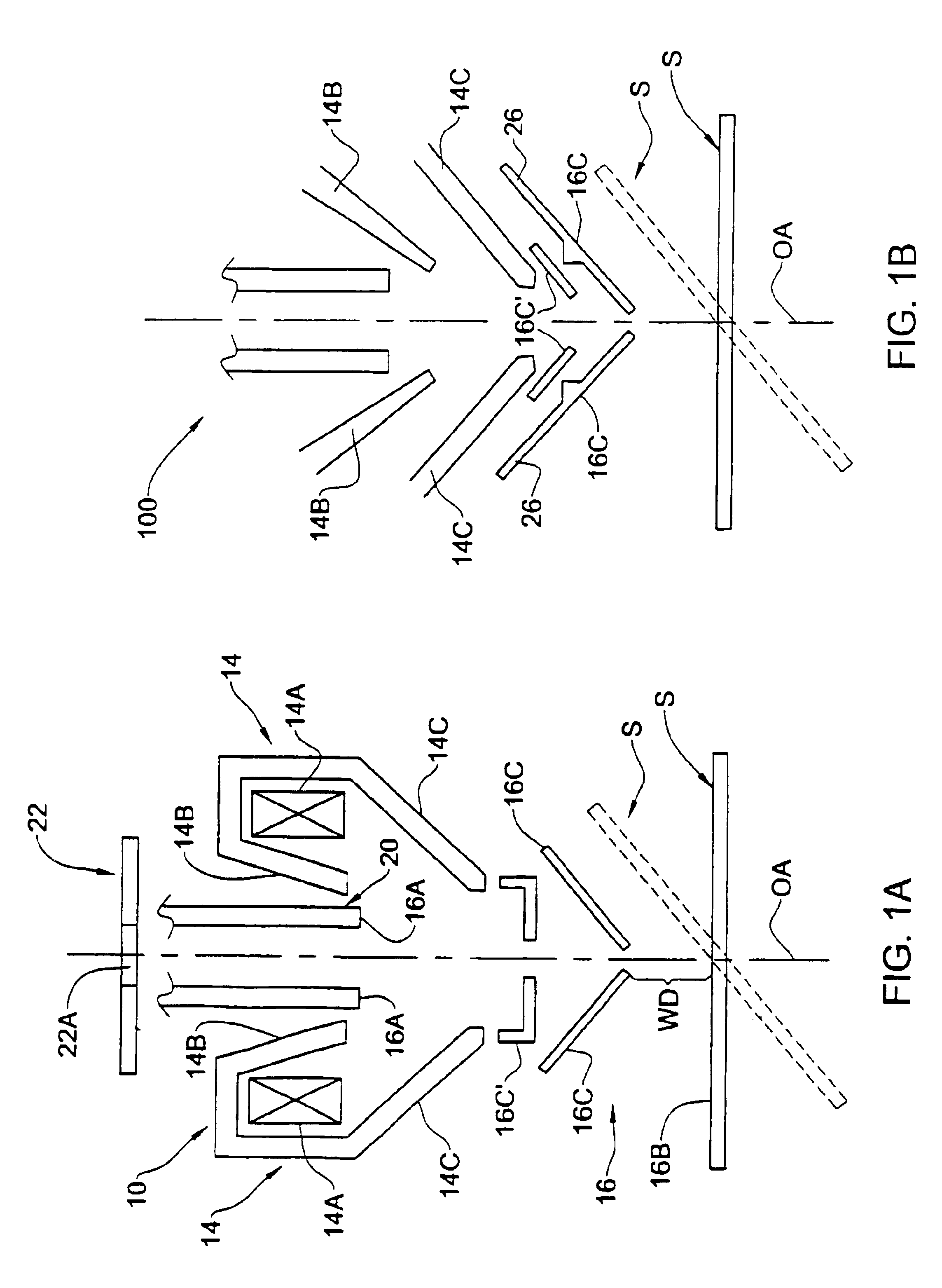
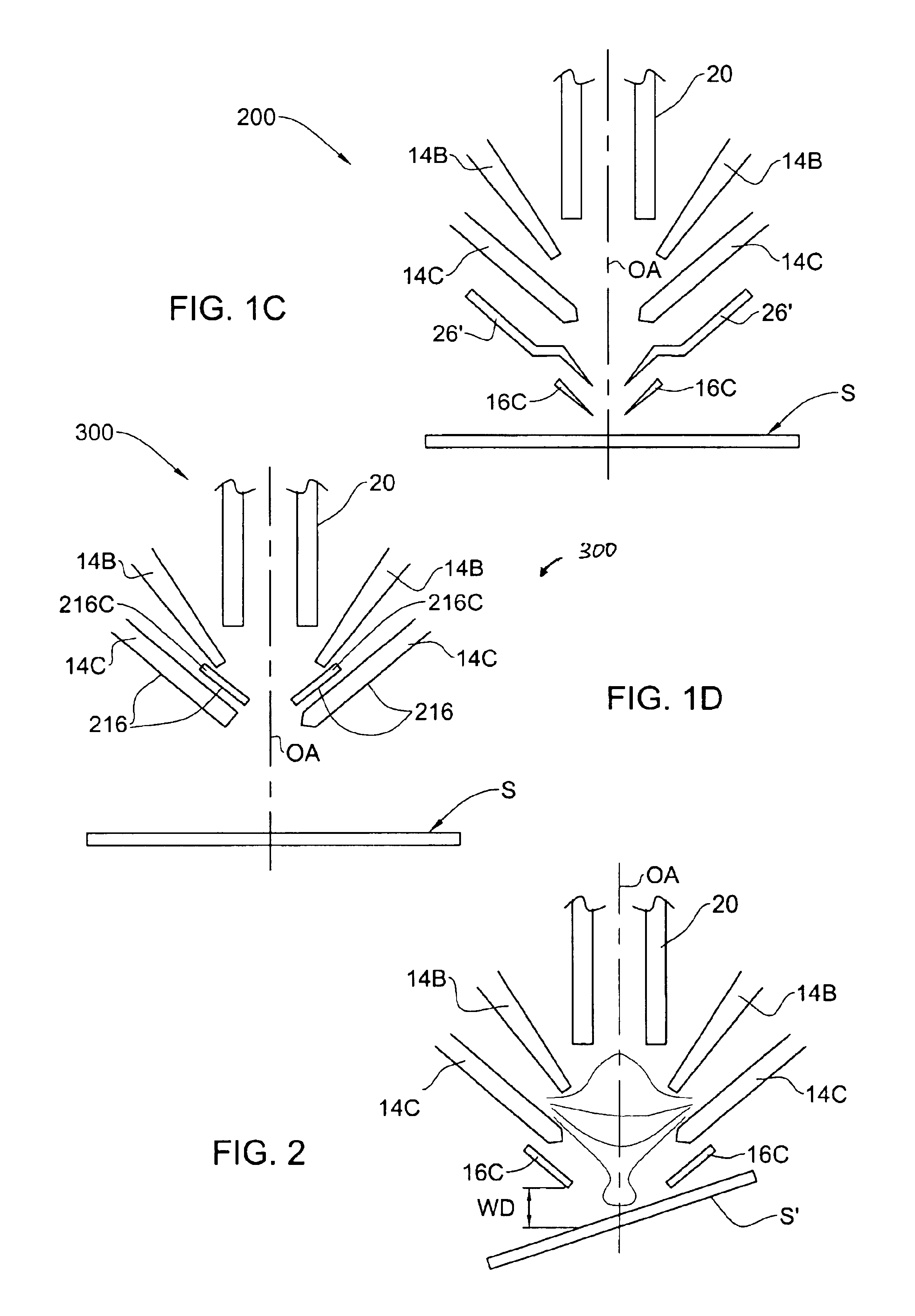
[0027]Referring to FIG. 1A, there is schematically illustrated a part of a charge particle beam column (such as an SEM) including an objective lens arrangement, generally at 10, associated with a sample S under inspection. The lens arrangement 10 includes a magnetic lens 14 and an electrostatic lens 16. Further provided in this part of the charged particle beam column is an in-lens detector 22 located above the lens 14 such that an optical axis OA of the lens arrangement passes through an opening 22A (primary beam hole) in the detector.

[0028]The magnetic lens 14 is formed by excitation coils 14A and two pole pieces 14B and 14C. The electrostatic lens 16 is formed by following electrodes: electrode 16A—the lower end of an anode tube 20, electrode 16B—the sample's surface, and “cap” electrodes 16C and 16′C arranged in a spaced-apart relationship along the optical axis OA of the lens arrangement between the electrodes 16A and 16B. The electrodes 16C and 16C′ are separately operated by ...


PUM


Abstract

An objective lens arrangement is presented for mounting in a charged particle beam column adjacent to an anode tube that defines a beam drift space for a charged particle beam propagating towards a sample. The lens arrangement comprises a magnetic lens and an electrostatic lens, wherein the electrostatic lens includes upper and lower electrodes arranged in a spaced-apart coaxial relationship along an optical axis of the lens arrangement.

Description

FIELD OF THE INVENTION[0001]The present invention is in the field of inspection / measurement techniques of the kind utilizing irradiation of a sample by a focused beam of electrically charged particles, such as electrons, positrons, or ions, and relates to an objective lens arrangement for use in a charged particle beam column.BACKGROUND OF THE INVENTION[0002]Charged particle beam columns are typically employed in scanning electron microscopy (SEM), which is a known technique widely used in the manufacture of semiconductor devices, being utilized in CD metrology tools, the so-called CD-SEM (Critical Dimension Scanning Electron Microscope) and defect review SEM (DR-SEM). In an SEM, the region of a sample to be examined is two-dimensionally scanned by means of a focused primary beam of electrically charged particles, usually electrons. Irradiation of the sample with the primary electron beam releases secondary (and / or backscattered) electrons. The secondary electrons are released at th...

Claims


Application Information

Patent Timeline
Patent Type & Authority Patents(United States)
IPC IPC(8): H01J37/28H01J37/10H01J37/145G01Q30/02
CPCH01J37/28H01J37/145
Inventor PETROV, IGOR
Owner APPL MATERIALS ISRAEL LTD
Why Eureka
Try Eureka