Transmitter device having a modulation closed loop

a transceiver and closed-loop technology, applied in the field of transceivers, can solve the problems of unnecessary transmission power, high cost of filtering, etc., and achieve the effects of preventing electromagnetic faults, rapid modulation, and rapid locking in characteristics

Inactive Publication Date: 2005-05-24
LUCENT TECH INC +1
View PDF11 Cites 45 Cited by
  • Summary
  • Abstract
  • Description
  • Claims
  • Application Information

AI Technical Summary

Benefits of technology

[0009]The advantage of a digital phase comparator consists in the fact that it compares signals in the baseband so that, in contrast to an analog phase comparator, no expensive high-speed phase comparators are required.
[0010]It is thus possible, for example, for the digital phase comparator which is used to be a digital phase / frequency discriminator which exhibits very rapid locking-in characteristics.
[0011]In order to obtain a baseband signal from the RF transmission signal, the converter device firstly has an analog / digital converter which is connected to an input of a complex digital multiplier. A controllable digital complex oscillator is connected to the other input of the complex digital multiplier. The controllable complex digital oscillator can be a numerically controlled oscillator (NCO) by means of which frequency jumps can be quickly modulated onto the RF transmission signal.
[0012]The analog / digital conversion and the downconversion of the RF transmission signal with respect to the baseband by means of the complex digital multiplier makes it possible to avoid processing the information in an intermediate frequency range, thus preventing electromagnetic faults which would occur with an analog embodiment of the modulation closed loop. Thanks to the digital downconversion of the RF signal and to the subsequent phase comparison of two baseband signals, very rapid frequency jumps, such as may be necessary in a GSM transmitter, are also permitted. The single limiting factor here is the bandwidth of the modulation closed loop itself. Consequently, when the modulation closed loop is embodied in a digital form there is no need, in contrast with an analog modulation closed loop, for expensive phase jump synthesizers, also referred to as hopping synthesizers. In addition, when the modulation closed loop is embodied in a digital form, phase errors, which would be caused by complex analog mixers and analog upconverters, are avoided.
[0013]In order to keep down the costs of the circuitry of the transmitter device, the digital signal processing of the modulation closed loop is carried out at a low clock frequency. For the same purpose, the converter device has a complex low-pass and decimating filter with which the sampling rate with which the RF transmission signal has been sampled is reduced.

Problems solved by technology

These filters are expensive owing to the required high level of signal coherence and steep edges, and the transmission power which can be effectively used is unnecessary owing to its insertion loss which has to be compensated again by a higher power output stage.

Method used


Image

  • Transmitter device having a modulation closed loop
  • Transmitter device having a modulation closed loop
  • Transmitter device having a modulation closed loop

Examples


Embodiment Construction

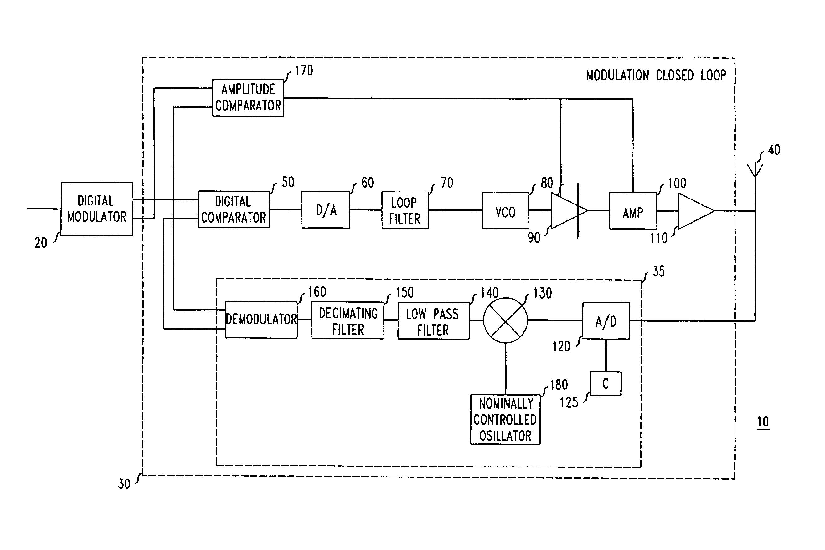
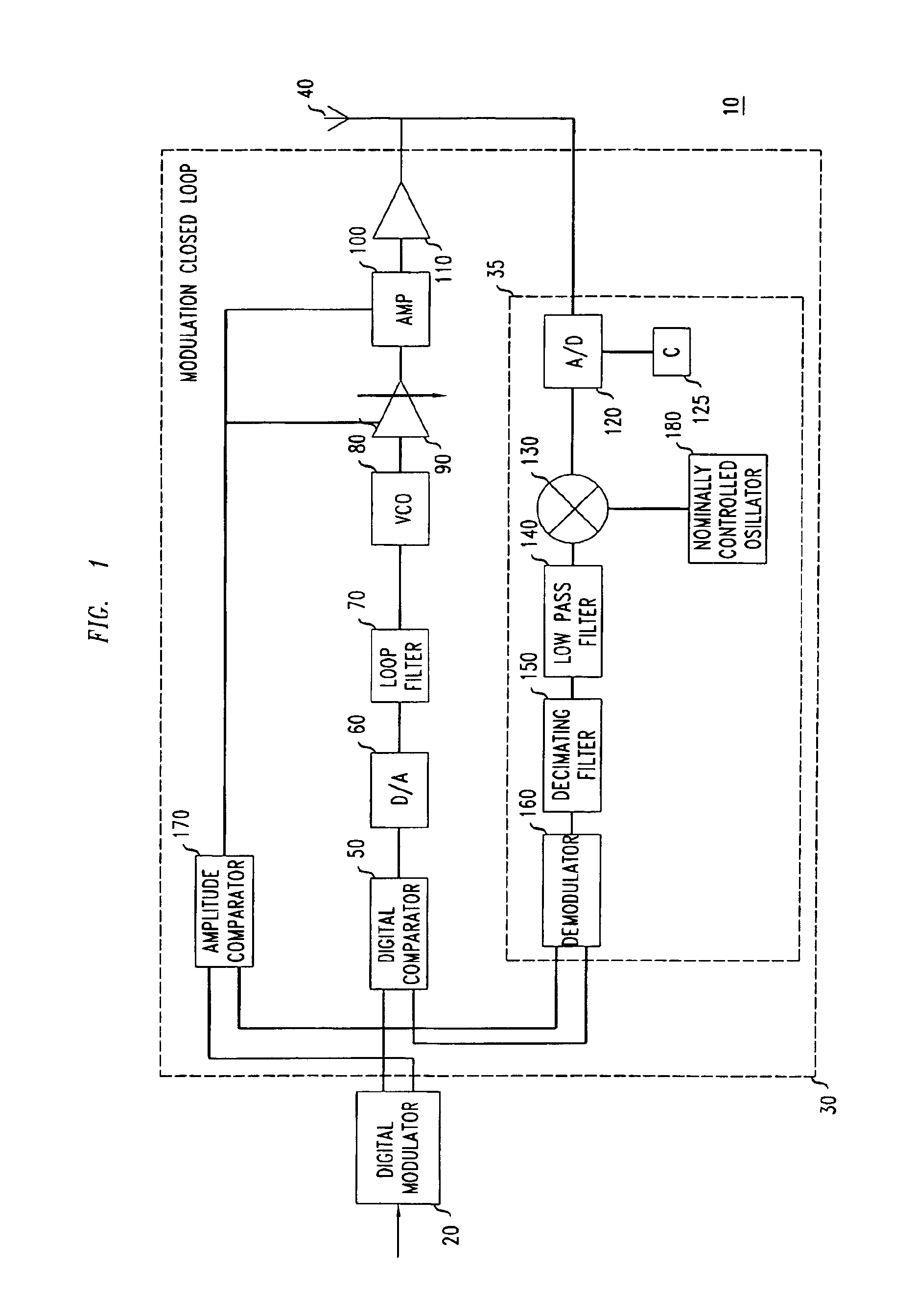
[0026]FIG. 1 shows a schematic block circuit diagram of an exemplary GSM (Global System for Mobile Communication) transmitter 10, which contains three essential functional blocks: a digital modulator 20, which may be embodied for example as 8-PSK modulator, a modulation closed loop 30, part of whose operations are digital, and a transmission antenna 40.

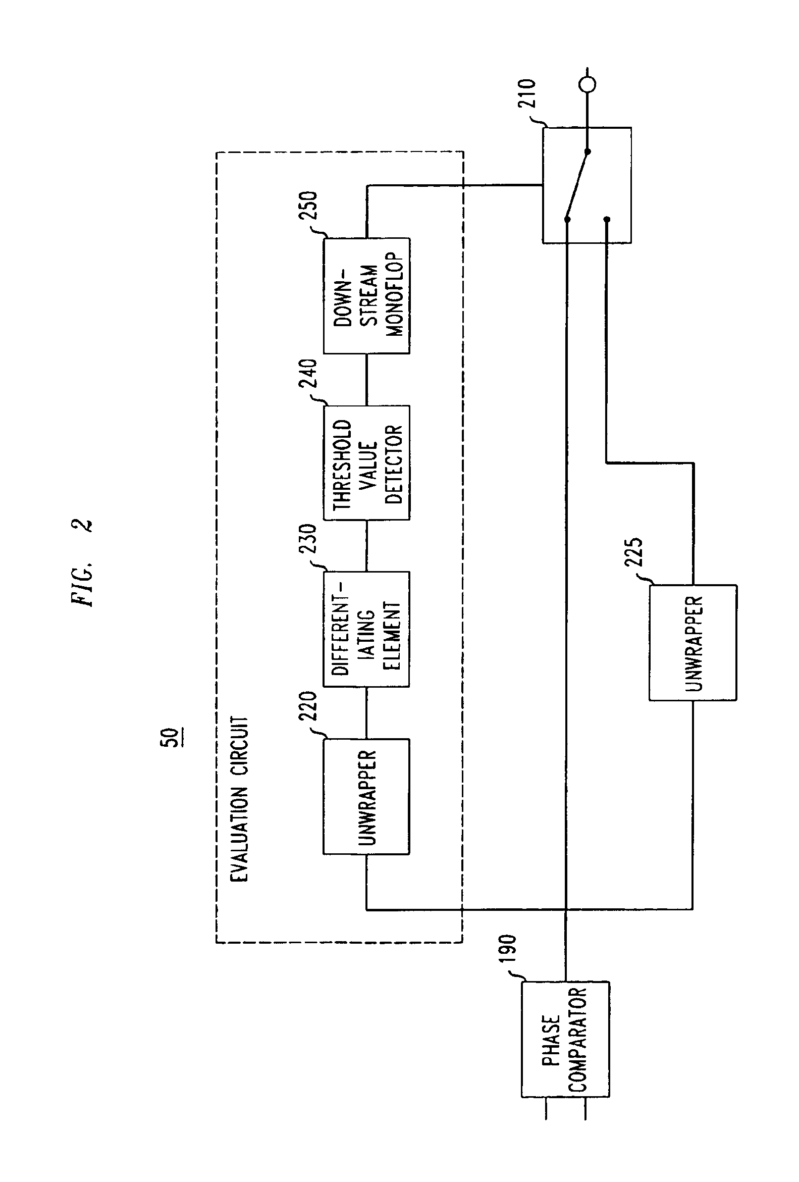
[0027]The modulation closed loop 30 has the function of mapping the digital input data stream supplied by the digital 8-PSK modulator 20 onto a high-precision 8-PSK-modulated RF signal which is broadcast by the transmission antenna 40. For this purpose, the modulation closed loop 30 has at the input end a digital phase comparator 50 which is preferably embodied as a phase / frequency discriminator. The design of the circuitry and the method of operation of the digital phase / frequency discriminator 50 are explained in more detail below with reference to FIG. 2. First, it is to be noted that the phase / frequency discriminator 50 can be ope...


PUM


Abstract

The invention relates, inter alia, to a transmitter device, in particular for a base transceiver station in a mobile radio system, which has a digital modulator for making available a signal containing a phase information, and a modulation closed loop having a digital phase comparator operating at baseband whose first input is connected to the output of the digital modulator. In addition, a controllable oscillator is provided for generating an RF transmission signal at a controllable transmission frequency, a device which is assigned to the controllable oscillator and has the purpose of converting the RF transmission signal into a baseband signal containing a phase information. The output of the converter device is connected to a second input of the digital phase comparator.A GSM transmitter which has such a modulation closed loop exhibits, in terms of its out-band noise and interference characteristics, significantly improved properties in comparison with a GSM transmitter which does not include a modulation loop.

Description

CROSS-REFERENCE TO RELATED APPLICATION[0001]This application claims priority of European Patent Application No. 00301545.0, which was filed on Feb. 28, 2000.BACKGROUND OF THE INVENTION[0002]1. Field of the Invention[0003]The invention relates to a transmitter device, in particular for a base transceiver station in a mobile radio network, a modulation closed loop which can be used in such a transmitter device, and a digital phase / frequency discriminator which is suitable for use in such a modulation closed loop.[0004]2. Related Art[0005]One of the most exacting requirements which is made of a GSM transmitter is its compliance with the GSM specifications in terms of the out-band noise and the interference of the GSM transmitter in the receiver band. The reason for this is the fact that the transmitter and receiver can be operating simultaneously and the separation between the transmitter band and the receiver band is 10 MHz at minimum. Hitherto, in order to comply with the specificati...

Claims


Application Information

Patent Timeline
Patent Type & Authority Patents(United States)
IPC IPC(8): H03C3/00H03C3/08H03C3/09H04L27/20H04B1/04
CPCH03C3/08H03C3/0925H03C3/0941H04L27/2017H03C3/0983H03C3/0991H03C3/0966H04B2001/0491
Inventor FISCHER, GEORGRIEMANN, VOLKER
Owner LUCENT TECH INC
Why Eureka
Try Eureka