DC motor with integral controller

a technology of dc motors and controllers, applied in the direction of electric controllers, steering initiations, vessel construction, etc., can solve the problems of limiting primarily, virtually any amount of heat produced by switches can be transferred to the environment, etc., to reduce the risk of electrical interference, and reduce the effect of electrical interferen

Inactive Publication Date: 2005-06-07
BRUNSWICK CORPORATION
View PDF8 Cites 45 Cited by
  • Summary
  • Abstract
  • Description
  • Claims
  • Application Information

AI Technical Summary

Benefits of technology

[0017]As will be apparent to those skilled in the art, with both the switch and the controller located in the motor hosing, the signal produced to drive the switch will suffer little, or no, degradation as opposed to routing the signal from an external controller to the motor housing. Furthermore, the emission of electromagnetic interference will be substantially reduced over either of the traditional methods.
[0018]As is known in the art, it is often desirable to locate a sonar transducer on a trolling motor. Unfortunately, the placement of a sonar transducer on or near a trolling motor has been somewhat problematic with prior art motors due to electromagnetic noise associated with the operation of the motor. When the trolling motor has a PWM controller, the interference associated with the motor is of particular concern. The inventive system will substantially ease the difficulties involved with such a combination.
[0019]Another advantage of the present system lies in the modularity of a trolling motor produced according to the present invention. A motor with an i...

Problems solved by technology

Thus, virtually any amount of heat which could be produced by the switch can be transferred to the e...

Method used


Image

  • DC motor with integral controller
  • DC motor with integral controller
  • DC motor with integral controller

Examples


Embodiment Construction

[0029]Before explaining the present invention in detail, it is important to understand that the invention is not limited in its application to the details of the construction illustrated and the steps described herein. The invention is capable of other embodiments and of being practiced or carried out in a variety of ways. It is to be understood that the phraseology and terminology employed herein is for the purpose of description and not of limitation.

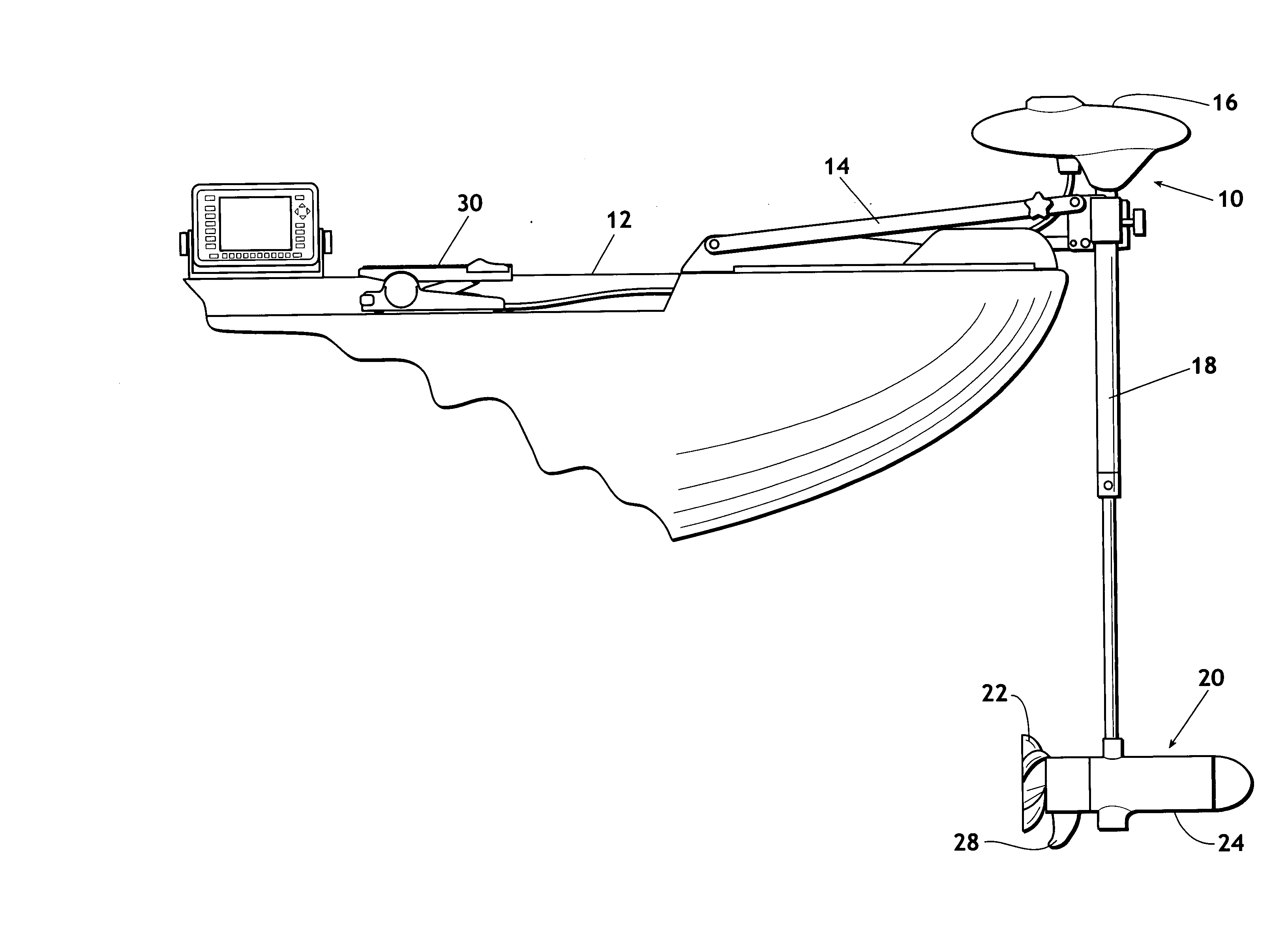
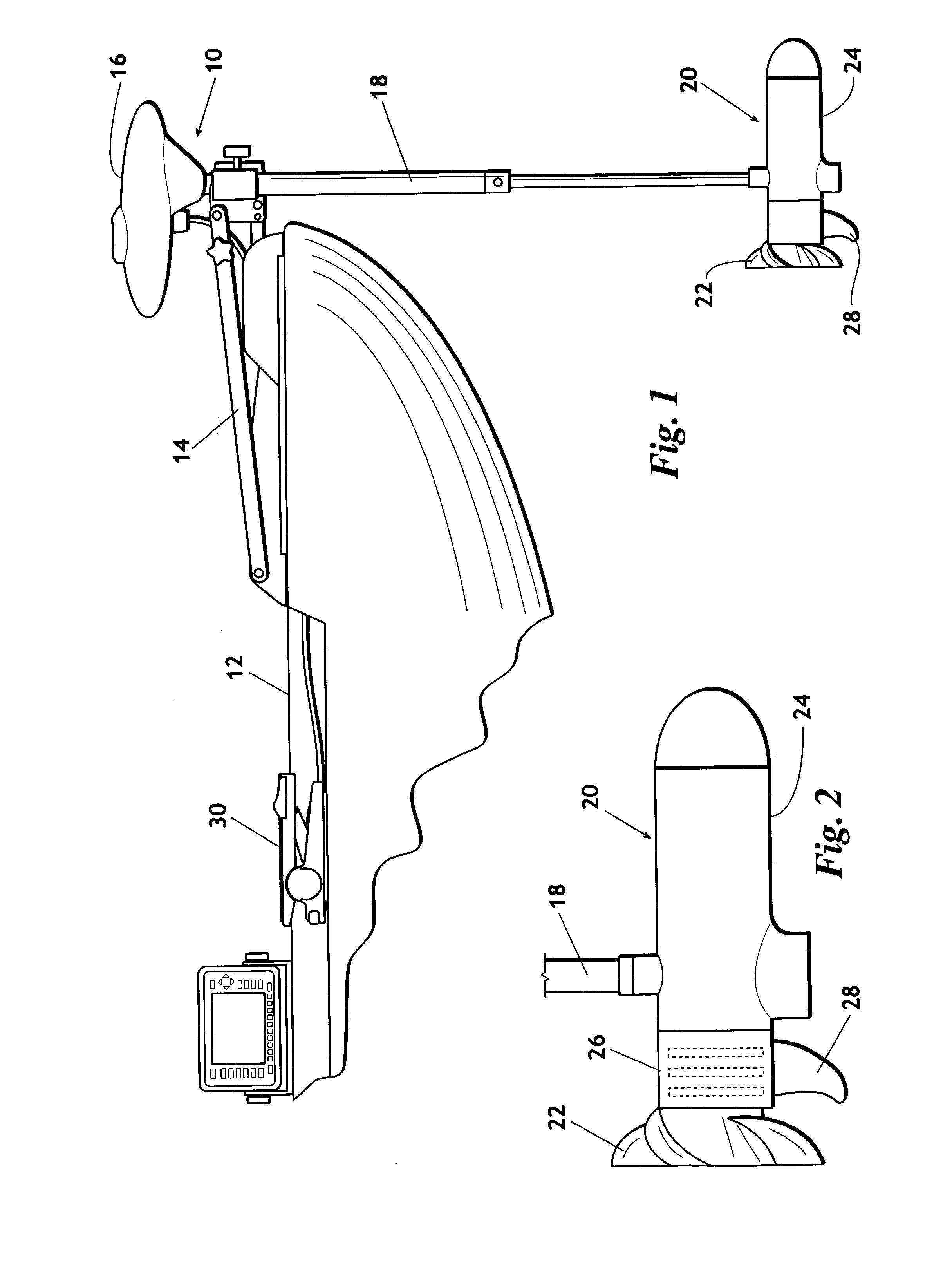
[0030]Referring now to the drawings, wherein like reference numerals indicate the same parts throughout the several views, a trolling motor 10 having an intrgral, submerged controller is shown in its general environment in FIG. 1. Typically trolling motor 10 is rotatably mounted to a fishing boat 12 by a mount 14. Mount 14 allows the trolling motor to be placed in the water, as shown in FIG. 1, or to be laid on the deck of boat 12 for when not in use. Preferably, trolling motor 10 includes: head 16 which typically houses a steering me...


PUM


Abstract

A DC motor having a motor housing and a motor controller housed within the motor housing. In a preferred embodiment the heat producing components of the motor controller are in thermal communication with the housing such that the majority of the heat produced by such components will be readily conducted to the environment in which the motor is operating. When incorporated into a trolling motor, the motor housing of the present invention will be submerged so that controller produced heat will be dissipated into the water in which the trolling motor is operated.

Description

BACKGROUND OF THE INVENTION[0001]1 Field of the Invention[0002]The present invention relates to DC motors. More particularly, but not by way of limitation, the present invention relates to a DC motor having a motor housing and a controller housed in the housing.[0003]2. Background of the Invention[0004]DC motors are well known in the art and are manufactured according to one of several constructions, i.e., permanent magnet type motors, wound-field type motors, brushless type motors, etc. Regardless of the type, when speed or torque control is required, a controller must be coupled with the motor. Presently, with permanent magnet or wound-field type motors, a separate controller is used. Normally such a controller provides a pulse width modulated output to vary the RMS voltage applied to the motor.[0005]Trolling motors are also well known in the art and, most often, employ a permanent magnet DC motor. Generally speaking, a trolling motor is a relatively small electric motor coupled t...

Claims


Application Information

Patent Timeline
IPC IPC(8): H02K5/132H02K11/00H02K11/02H02K23/66
CPCH02K23/66H02K11/0073H02K5/132H02K11/022H02K11/33H02K11/02H02K11/01
Inventor HEALEY, ROBERT W.
Owner BRUNSWICK CORPORATION
Why Eureka
Try Eureka