Ion detector

a technology of ion detector and microchannel plate, which is applied in the field of ion detector, can solve the problems of reducing the bandwidth of the collection anode, reducing the voltage difference between the microchannel plate(s) and the collection anode, and reducing the bandwidth of the signal induced ringing noise of the collection anode, so as to reduce the detrimental effect of electric fields, reduce the voltage difference between the microchannel plate(s) and the collection anode, and the effect of ion

Active Publication Date: 2005-06-14
MICROMASS UK LTD
View PDF10 Cites 17 Cited by
  • Summary
  • Abstract
  • Description
  • Claims
  • Application Information

AI Technical Summary

Benefits of technology

[0060]A lens system may be arranged between the microchannel plate(s) and the collection anode. In one embodiment the lens system may direct or guide electrons from the output surface of the microchannel plate(s) to the input surface of the collection anode. This enables the voltage difference between the microchannel plate(s) and the collection anode to be reduced whilst still transferring the electrons from the microchannel plate(s) to the collection anode efficiently. The lens system also enables electrons to be directed or guided to the collection anode with negligible spreading in the electron flight times by the anode. The lens system also preferably reduces the detrimental effect of electric fields penetrating into the region between the microchannel plate(s) and collection electrode. This is a particular problem when a microchannel plate ion detector is used in a Time of Flight mass spectrometer wherein the flight tube of the Time of Flight mass spectrometer is floated at a relatively high voltage.
[0061]In another embodiment the lens system may be operated in a defocusing mode in order to control the overall gain of the ion detector or to blank out amplified signals which are likely to saturate a detection system which includes a Time to Digital Converter. The lens system may also be operated in a defocusing mode so that electrons that are released from certain areas of the microchannel plate are selectively directed or guided to the

Problems solved by technology

In particular, conventional microchannel plate ion detectors suffer from signal induced ringing noise and/or reduced bandwidth caused by impedance mismatching between the collection anode which collects electrons from the microchannel plate(s) and the 50 Ω input amplifier of the Analogue to Digital Converter or the Time to Digital Converter used as part of the acquisition electronics.
Another disadvantage of conventional microchannel plate ion detectors results from the requirement that Time of Flight mass spectrometers are designed to mass analyse ions having relatively high kinetic energies, typically several keV.
However, conventional approaches to capacitively decoupling the collection anode from the Analogue to Digital Converter or the Time to Digital Converter cause impedance mismatching between the collection anode and the

Method used


Image

  • Ion detector
  • Ion detector
  • Ion detector

Examples


Embodiment Construction

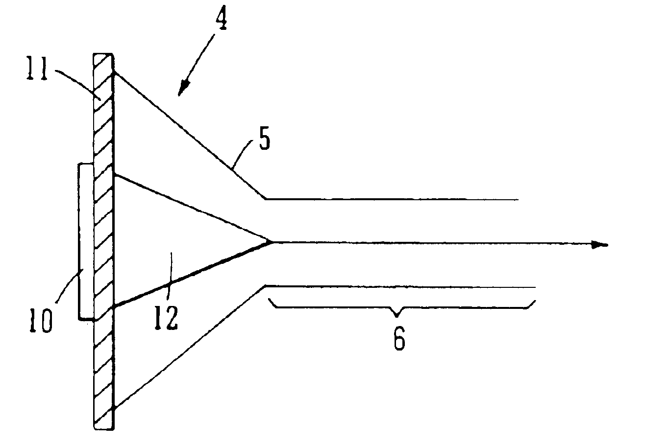
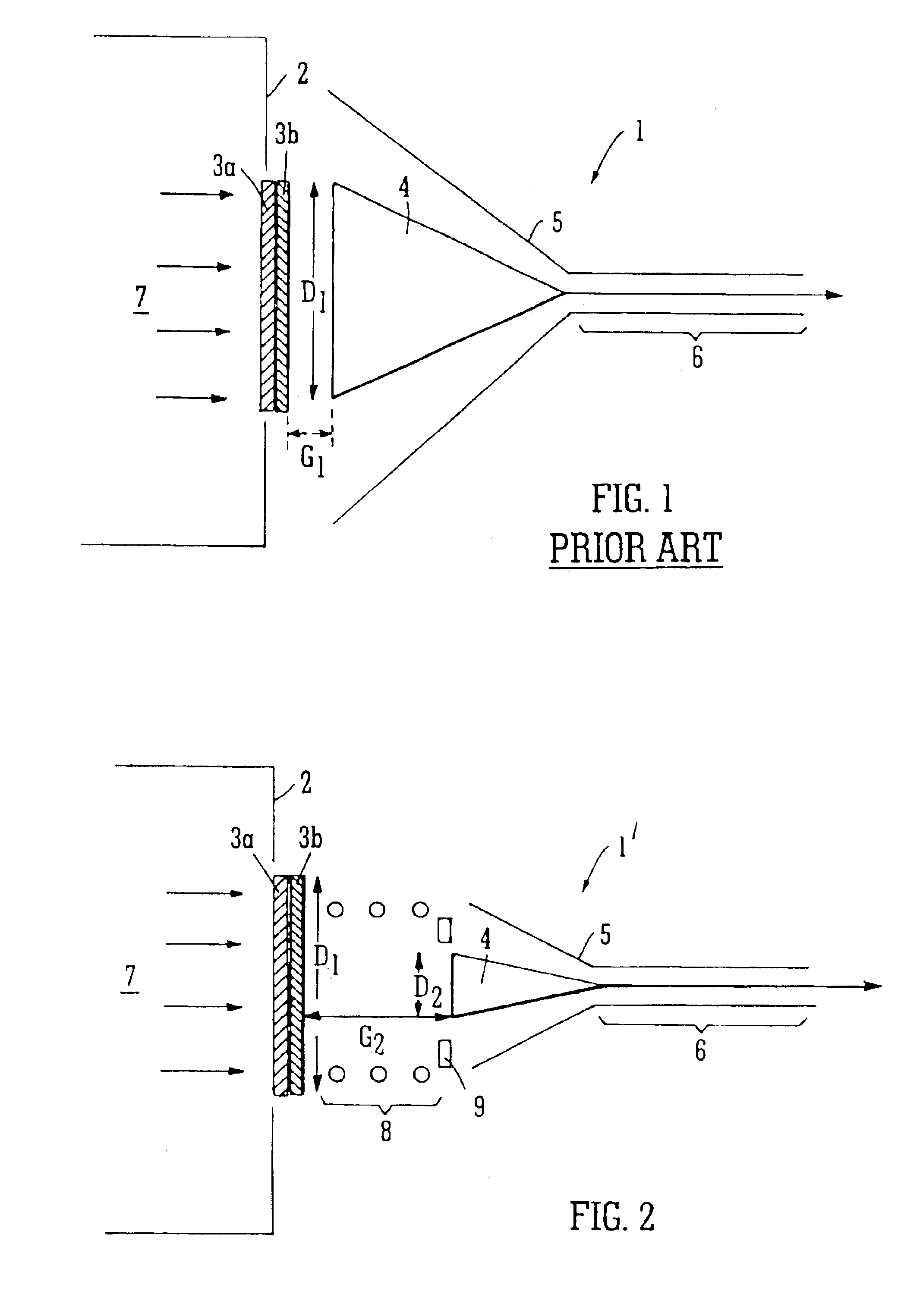
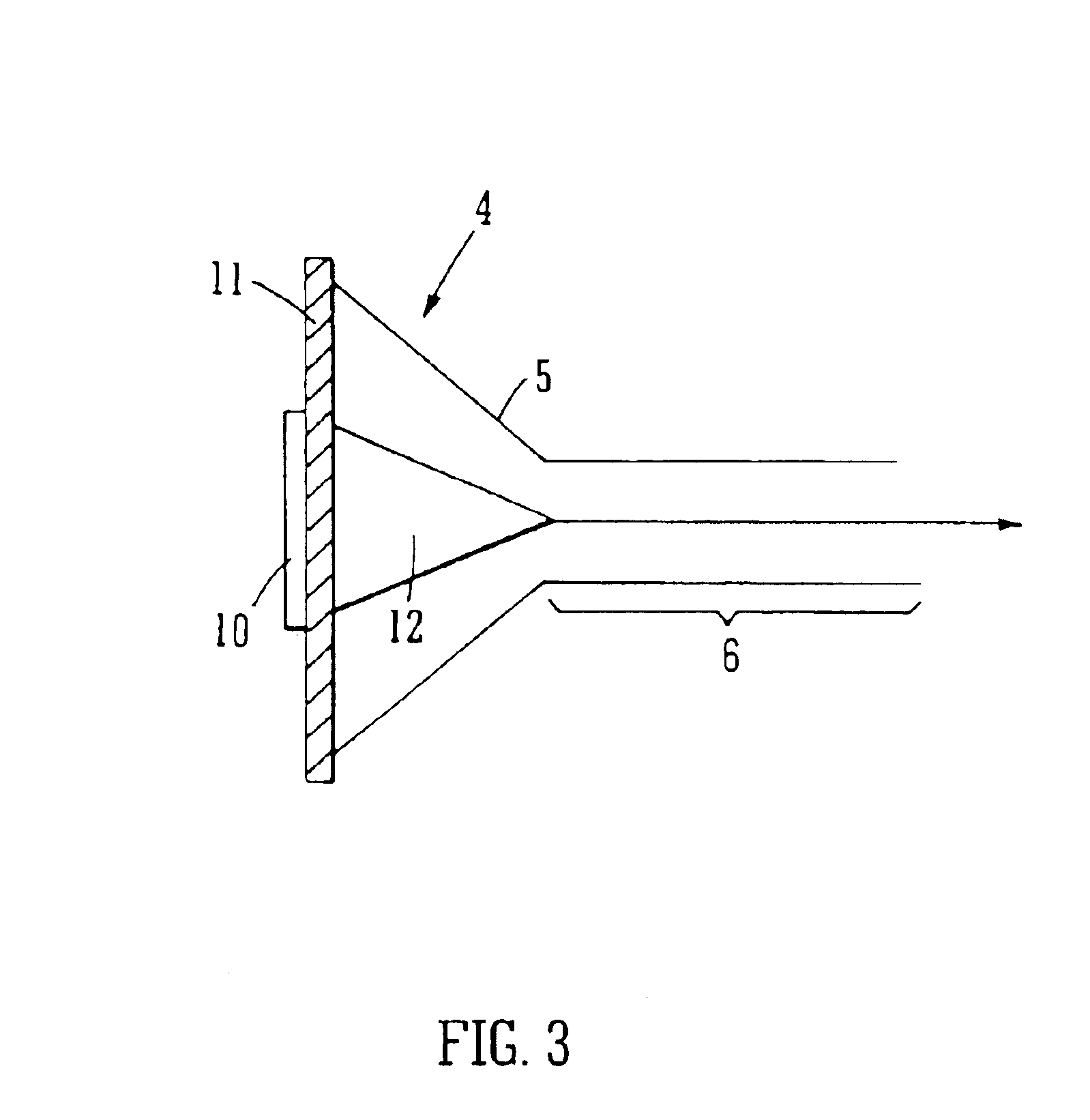
[0076]A conventional microchannel plate ion detector 1 is shown in FIG. 1 and comprises two microchannel plates 3a,3b arranged to receive ions 7 from a flight tube 2 of a Time of Flight mass analyser. The two microchannel plates 3a,3b are arranged in contact with each other and with the channels of the two microchannel plates being angled with respect to the interface between the microchannel plates 3a,3b. Ions 7 arriving at the ion detector 1 strike an input surface of the first microchannel plate 3a causing multiple electrons to be generated by the microchannel plate 3a. These electrons cause further cascading of electrons from the second microchannel plate 3b. The electrons generated by the microchannel plates 3a,3b then exit the rearmost microchannel plate 3b and are subsequently collected by a conical collection anode 4 arranged slightly downstream of (i.e. 5-10 mm from) the rearmost microchannel plate 3b. The output surface of the rearmost of the two microchannel plates 3b and...


PUM


Abstract

An ion detector for a mass spectrometer is disclosed comprising one or more microchannel plates and an anode arranged to receive electrons emitted from the one or more microchannel plates. The anode is permanently magnetized and electrons emitted from the microchannel plates preferably spiral around lines of magnetic field towards the anode.

Description

CROSS REFERENCE TO RELATED APPLICATION[0001]This application claims priority from U.S. Provisional Application 60 / 433,023, filed Dec. 13, 2002 and United Kingdom Patent Application 0229001.3, filed Dec. 12, 2002. The contents of these applications are incorporated herein by reference.STATEMENT OF FEDERAL SPONSORED RESEARCH[0002]N / AFIELD OF INVENTION[0003]The present invention relates to an ion detector for use in a mass spectrometer, a mass spectrometer, a method of detecting ions and a method of mass spectrometry.BACKGROUND OF INVENTION[0004]Commercial high performance Time of Flight mass spectrometers generally utilise ion detection systems comprising microchannel plates for pre-amplifying ion pulse signals. Microchannel plates generate multiple electrons in response to an ion striking the input surface of the microchannel plate. The electrons which are generated by the microchannel plate provide an amplified signal which may then be subsequently recorded using a fast Analogue to ...

Claims


Application Information

Patent Timeline
IPC IPC(8): B01D59/44B01D59/00G01K1/08H01J49/00
CPCH01J43/246
Inventor BATEMAN, ROBERT HAROLDBROWN, JEFFKENNY, DANIEL JAMES
Owner MICROMASS UK LTD
Why Eureka
Try Eureka