Photo-receiver arrangement

a photoreceiver and receiver technology, applied in the field of photoreceiver arrangement, can solve the problems of large design constraints, signal level below the lower bound of the dynamic range is difficult to detect, and the transimpedance amplifier is not able to accommodate the wide dynamic range of photocurrent, so as to achieve the effect of large dynamic rang

Inactive Publication Date: 2005-06-14
LITE ON TECH CORP
View PDF10 Cites 15 Cited by
  • Summary
  • Abstract
  • Description
  • Claims
  • Application Information

AI Technical Summary

Benefits of technology

[0013]One of the features of the invention is to provide a photo-receiver arrangement capable of capturing and processing incident light having a large dynamic range in an accurate manner.
[0014]Another feature of the present invention is to provide a photo-receiver arrangement that is less susceptible to the problems based on the constraints in sensitivity, SNR, bandwidth and stability of the known devices, and that has a low power dissipation being necessary for battery operated portable electronic devices like hand phones, personal digital assistants (PDA), laptops, etc.

Problems solved by technology

As such, the transimpedance amplifier is not able to accommodate the wide dynamic range of the photocurrent generated by the IR sensor without losing its linearity.
Any signal with a signal level below the lower bound of the dynamic range will be very difficult to detect, as the SNR is very low in this range.
Further, the bandwidth requirement places a large constraint on the design of the transimpedance amplifier 200.
However, this is not so easy as the values of Cf 230 and Rf 220 themselves are also subject to various constraints.
With such a high Cpd 110, the circuit might have stability problems.
However, increasing the value of the feedback capacitor Cf 230 also decreases the bandwidth, resulting in increased distortion of the input signal.
One problem of this implementation is that since the dynamic range of the input photocurrent is very large as explained above, a feedback resistor Rf 220′ with a plurality of different values is needed to achieve a sufficient number of gain steps.
Another problem is that this known implementation operates with high current values and has, therefore, high power dissipation.
One drawback of this known diode clamping transimpedance circuitry 400 is that it is only suitable for low speed implementations.

Method used


Image

  • Photo-receiver arrangement
  • Photo-receiver arrangement
  • Photo-receiver arrangement

Examples


Embodiment Construction

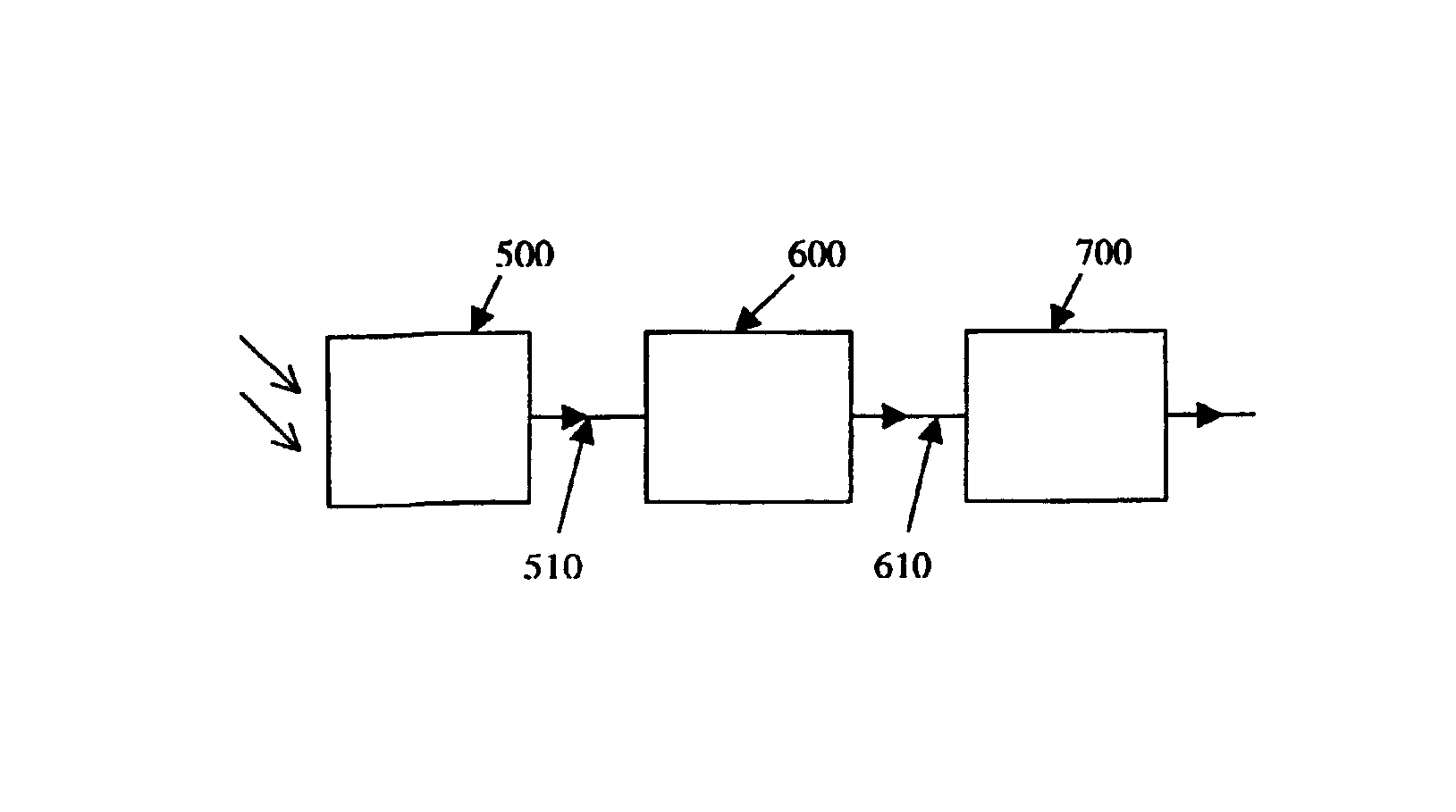
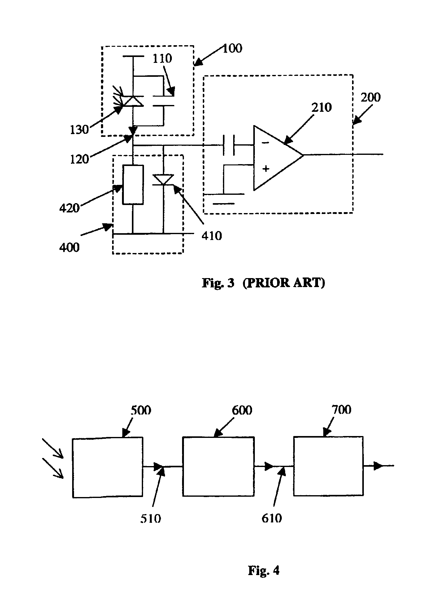
[0024]FIG. 4 shows a photo-receiver arrangement that includes a photo-sensor 500, a pre-scaler 600 and a preamplifier 700. The photo-sensor 500 captures light being incident thereon and having a predetermined range of light intensity values, and converts the captured incident light into a first electrical signal. The pre-scaler 600 is connected to an output of the photo-sensor for producing a second scaled electrical signal based on and corresponding to the first electrical signal which is input into the pre-scaler 600. The preamplifier 700 is connected to an output of the pre-scaler 600 to amplify the second scaled electrical signal which is input into the preamplifier 700. The preamplifier 700 has a dynamic range of at least substantially linear gain. The pre-scaler 600 and the preamplifier 700 are designed in a mutually matching configuration such that the second scaled electrical signal falls within the dynamic range of the preamplifier 700 for any light intensity value falling ...


PUM


Abstract

A photo-receiver arrangement includes a photo-sensor that captures light being incident thereon within a predetermined range of light intensity values. The photo-sensor also converts the captured incident light into a first electrical signal. A pre-scaler is connected to an output of the photo-sensor for producing a second scaled electrical signal based on and corresponding to said first electrical signal input into the pre-scaler; and a preamplifier is connected to an output of the pre-scaler for amplifying said second scaled electrical signal input into the preamplifier. The preamplifier has a dynamic range of at least substantially linear gain. The pre-scaler and the preamplifier are designed in a mutually matching configuration such that the second scaled electrical signal falls within the said dynamic range of the preamplifier for any light intensity value falling into said predetermined range of light intensity values.

Description

FIELD OF THE INVENTION[0001]The invention relates to a photo-receiver arrangement having a photo-sensor and a preamplifier for detecting and measuring light, in particular infrared light being incident on the photo sensor.BACKGROUND OF THE INVENTION[0002]Infrared (IR) technology is one kind of wireless technology that is commonly utilized in electronic devices, like laptop computers, hand phones and PDAs (personal digital assistant) due to its low cost of implementation and high data transfer rates in the order of Mb / s. IR technology allows users to link to each other through various IR devices over a short distance. Generally, known IR devices comprise an IR transceiver for transmitting, receiving and processing an infrared signal. The IR transceiver including an IR sensor for capturing IR light and converting the same into an electrical signal, and a preamplifier for amplifying the electrical signal generated by the IR sensor. The power of the incident infrared light varies in ord...

Claims


Application Information

Patent Timeline
Patent Type & Authority Patents(United States)
IPC IPC(8): G01J1/44H03F3/08H04B10/07H04B10/116H04B10/40H04B10/50H04B10/60H04B10/69
CPCG01J1/44
Inventor QUEK, IRENE
Owner LITE ON TECH CORP
Why Eureka
Try Eureka