
Circuit with voltage clamping for bias transistor to allow power supply over-voltage

a bias transistor and circuit technology, applied in the field of electrical circuits, can solve the problems of affecting the reliability of the transistor, the power supply voltage of the transistor-based circuit that employs a certain manufacturing technology, and the practical limitations of the power supply voltage, so as to improve circuit performance, reduce breakdown voltage ratings, and increase output voltage swing

Inactive Publication Date: 2005-06-28
MACOM CONNECTIVITY SOLUTIONS LLC
View PDF2 Cites 11 Cited by
  • Summary
  • Abstract
  • Description
  • Claims
  • Application Information

AI Technical Summary

Benefits of technology

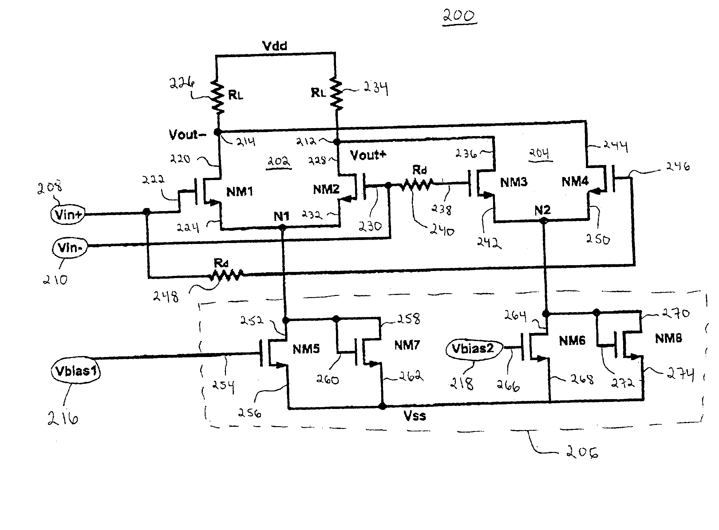
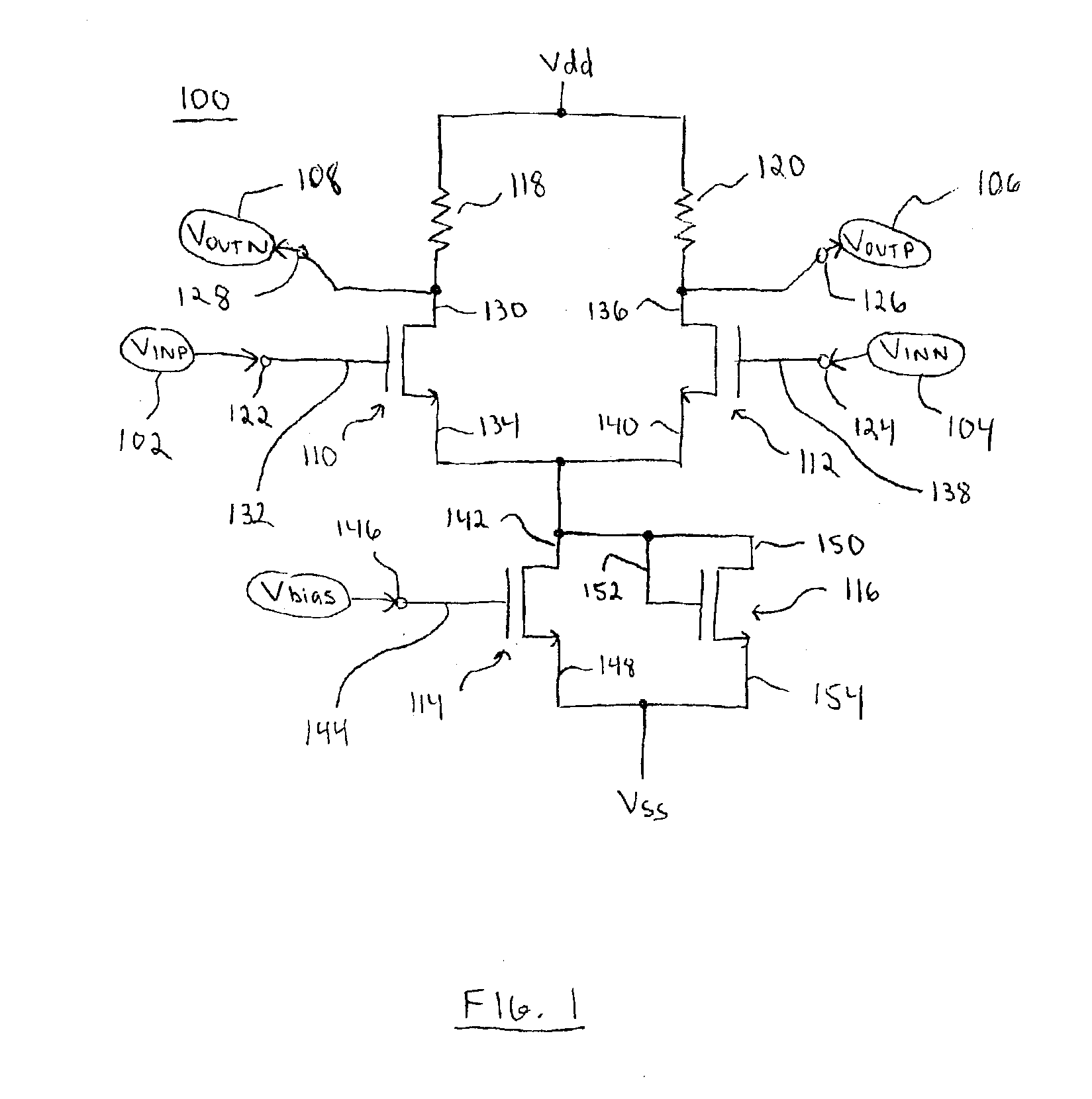
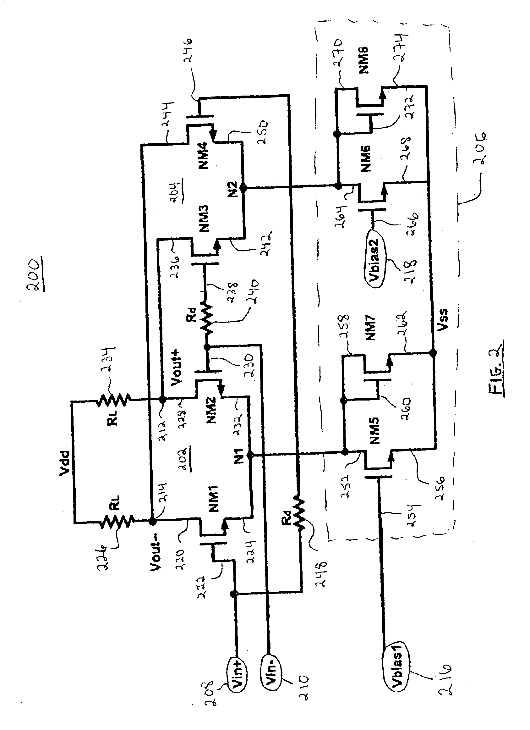
[0005]A transistor-based electronic circuit according to the invention is designed to utilize a power supply voltage that exceeds the breakdown voltage for the given transistor technology, while still satisfying the reliability requirements for the transistors. The higher power supply voltage results in an increased output voltage swing, which corresponds to improved circuit performance (due to a reduction in output noise). This feature can be very desirable in high speed applications that require fast transistors having lower breakdown voltage ratings.

Problems solved by technology

Traditionally, transistor-based circuits that employ a certain manufacturing technology have practical limitations on the power supply voltage.
If the breakdown voltage is exceeded, then the reliability of the transistors can be adversely affected and performance of the circuit can suffer.
Unfortunately, circuit design restrictions do not always allow the use of an unlimited power supply voltage.

Method used


Image

  • Circuit with voltage clamping for bias transistor to allow power supply over-voltage
  • Circuit with voltage clamping for bias transistor to allow power supply over-voltage
  • Circuit with voltage clamping for bias transistor to allow power supply over-voltage

Examples


Embodiment Construction

[0011]The present invention may be described herein in terms of functional block components and various processing steps. It should be appreciated that such functional blocks may be realized by any number of hardware, software, and / or firmware components configured to perform the specified functions. In addition, those skilled in the art will appreciate that the present invention may be practiced in conjunction with any number of data communication systems and that the particular oscillator circuit described herein is merely one exemplary application for the invention.

[0012]It should be appreciated that the particular implementations shown and described herein are illustrative of the invention and its best mode and are not intended to otherwise limit the scope of the invention in any way. Indeed, for the sake of brevity, conventional aspects of the circuits (and the individual operating components of the circuits) may not be described in detail herein. Furthermore, the connecting li...


PUM


Abstract

A ring oscillator stage includes two differential transistor pairs configured to add an adjustable amount of delay to a differential input signal. Each differential pair is biased with a bias current transistor; the bias current transistor is “protected” by a voltage-clamping transistor that limits the drain voltage of the bias current transistor. The voltage-clamping transistors enable use of a power supply voltage (VDD) that would otherwise exceed the reliability breakdown voltage limit of the bias current transistors.

Description

FIELD OF THE INVENTION[0001]The present invention relates generally to electronic circuits. More particularly, the present invention relates to CMOS differential pair circuits.BACKGROUND OF THE INVENTION[0002]The prior art is replete with transistor-based electronic circuits designed to support high speed data communication applications. Traditionally, transistor-based circuits that employ a certain manufacturing technology have practical limitations on the power supply voltage. In this regard, the power supply voltage should not exceed the “breakdown” voltage (which is determined by the particular manufacturing technology) for the transistors. If the breakdown voltage is exceeded, then the reliability of the transistors can be adversely affected and performance of the circuit can suffer.[0003]In some circuits, the power supply voltage is related to the quality of the output signal(s). For example, in a ring oscillator stage, a higher power supply voltage (VDD) results in a higher o...

Claims


Application Information

Patent Timeline
Patent Type & Authority Patents(United States)
IPC IPC(8): H03B27/00H03K3/03H03K17/0814
CPCH03K17/08142H03K3/0322
Inventor LI, WEIBRYAN, THOMAS CLARKLIU, ZHIXIANG JASON
Owner MACOM CONNECTIVITY SOLUTIONS LLC
Learn More