Method and apparatus to monitor, control and log subsea oil and gas wells

a technology for monitoring, controlling and logging subsea wells, applied in the direction of survey, instrumentation, borehole/well accessories, etc., can solve the problems of difficult to log or access subsea wells, high drilling cost, and inconvenient operation

Inactive Publication Date: 2005-07-05
SENSOR HIGHWAY LTD
View PDF37 Cites 53 Cited by
  • Summary
  • Abstract
  • Description
  • Claims
  • Application Information

AI Technical Summary

Benefits of technology

[0024]This invention further teaches the connection of the alternative path conduits to a surface instrument pod by connecting continuous conduit from the conduit proceed forth from the sub sea well and wellhead terminating at the hydraulic wet connects, where the inventions surface instrument pod remains on station above the sub-sea well at the sea surface. The invention further teaches that the instrument pod can have recording, processing and transmission devices inside the pod where the devices record, processes, and transmits the data and information to receiving locations on land or offshore. The use of an umbilical connected back to a remote surface instrument pod from the alternative path conduit disposed in the sub-sea well avoids the need for long umbilical cables back along the sea floor to the host production facility miles from the sub sea well. An additional feature of this invention permits remote data transmission and well interaction. Commands can be transmitted from a remote station to the surface instrument pod, and then down the umbilical disposed in the sea, and into to the sub-sea well for the purpose of operating downhole devices, such as valves, gauges, sensors and the like in response to these remote commands.

Problems solved by technology

Often, the well products have to travel many miles from the subsea well head to such storage facilities
As oil and gas becomes more and more difficult to find on land or in shallow coastal waters, the oil and 
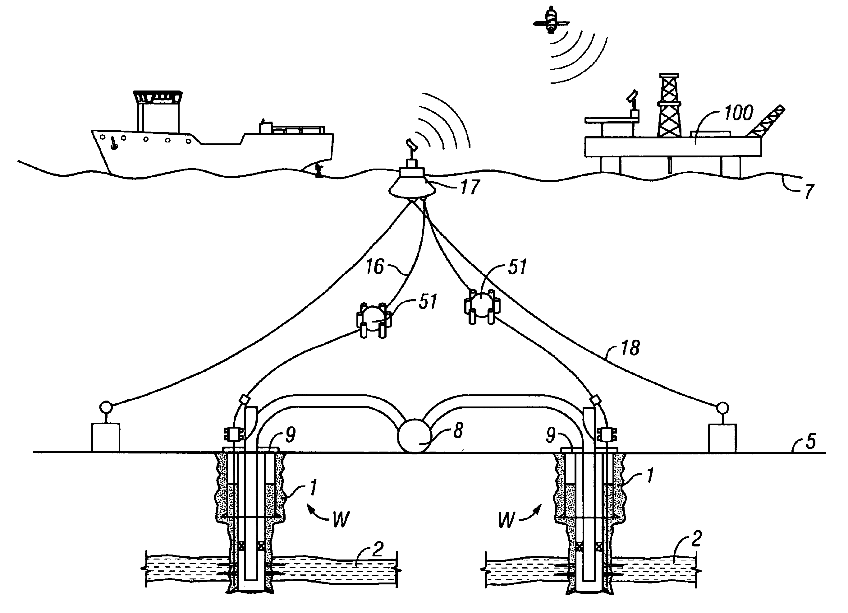
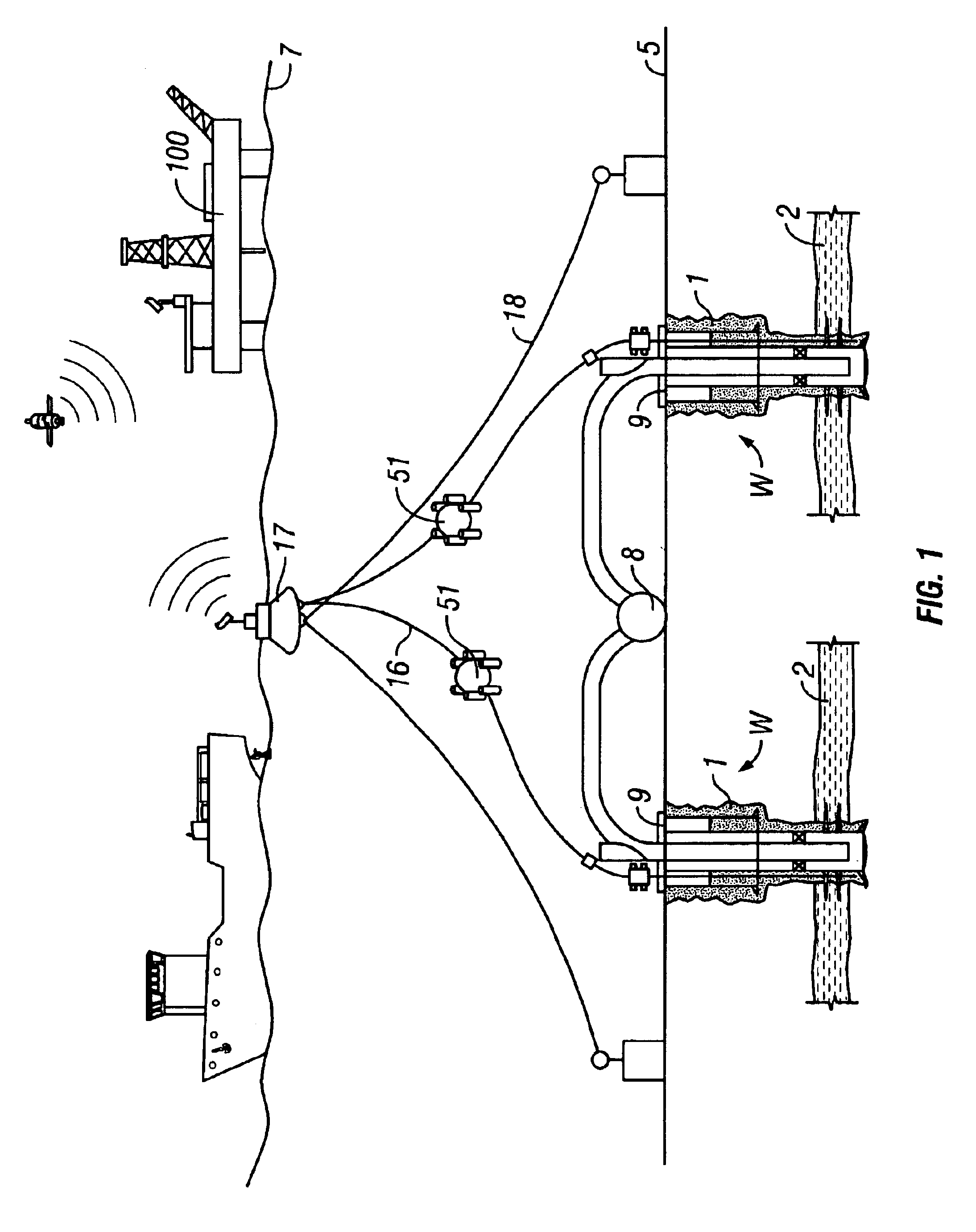
gas industry has commenced exploration and development in deeper waters, miles from production and storage facilities.
Obtaining access to subsea wells for logging, monitoring or control purposes generally requires a costly submersible connection from the sea surface to the wellhead.
Because such wells are very expensive to drill and bring on line, most oil and gas producers prefer to not reenter the well unless absolutely necessary.
Hence, subsea wells are difficult to log or access for the placement of monitoring equipment.
Further, visual inspections of these subsea wells are impossible because of the depths and distances of the wellhead from the nearest maintenance and production platform facility.
Because of the long distances and depths, considerable expense must be incurred to utilize these subsea umbilicals.
Furthermore, the current monitoring methods to monitor subsea wells are further compromised by frequent failure of various subterranean gauges and instruments used to monitor oil and gas wells.
Because of the remoteness of subsea wells from the surface of the sea and the need for rig interventions to access the subsea and subterranean monitoring devices, they require well maintenance to be performed from intervention rigs which are not always immediately available to perform such maintenance.
The result of these failures and the difficulty of quickly repairing them generally results in the decision to continue producing deep-water wells without any subsea monitoring information for leaks and pressure anomalies and without subterranean monitoring of reservoir parameters.
Such shortcuts are undesirable because they can lead to catastrophic failures of wells, hydrocarbon releases into the sea, and less than optimal reserve recovery.
In subsea wells, logging is rarely done, as it requires the mobilization of very large and expensive semi-submersible rigs or drill ships.
Furthermore, these subsea logging interventions introduce the possibility of losing wireline equipment in the well and compromising the well's ability to produce.
Because of the above-mentioned difficulties of logging and maintaining unreliable subterranean monitoring equipment and very long umbilical transmission lines, many sub-sea wells are produced while monitoring the produced fluid back at the process or storage facility many miles away.
This monitoring does not yield any indication of where the fluids are coming from in the well (i.e. which portion of the formation may be producing) which may be desired where production may be resulting from large perforated intervals in the well.
Additionally, flow rate information monitored at the surface does not identify possible cross flow of fluids between reservoir intervals, changes in water, oil, and gas quantities as function of the depth of the well, the presence of leaks in well tubular conduits, and whether the reservoir is depleting in pressure.
However, in the case of sub-sea wells the methods have to date not been developed to allow for safe, simple, and rapid log intervention into wells.
Failure and need for retrieval of subterranean pressure gauges or other subterranean instruments in sub-sea wells can not be performed by wire line or logging interventions unless a semi-submersible rig or drill ship is deployed to the sub-sea well location.
These connections are difficult to do at deep-water depths, which often have large currents, high hydrostatic pressures, and are at depths where only a very limited number of Remotely Operated Vehicles (ROVs) can operate and make such wet connections.
This results in very long umbilicals with large weights and costs.
When the pressure gauge fails or when the data transmission line fails, or when the data transmission's wet-mateable connection fails, the only recourse for repair of the data gathering system is an intervention into the well, using either a drill ship or a semi-submersible drilling rig resulting in the pulling of the well completion, and a significant number of days of lost production during the recompletion of the well, all as previously described.
The intrusion of logging tools into the flow stream of such wells presents a significant risk of losing the logging equipment in the well and obstructing fluid production.

Method used


Image

  • Method and apparatus to monitor, control and log subsea oil and gas wells
  • Method and apparatus to monitor, control and log subsea oil and gas wells
  • Method and apparatus to monitor, control and log subsea oil and gas wells

Examples


Embodiment Construction

The Alternative Path Conduit

[0028]Referring now to FIG. 1 of the drawings, a plurality of wells W are shown located on the sea floor 5. The well is drilled from the surface of the sea 7 using a semi-submersible 100 or drillship drilling rig (not shown). One or more wells W are bored by the action of rotating a drill bit on the end of a drill pipe from the surface rig where the drill bit is inserted inside of risers pipes and the drill cuttings are flushed out of the well bore with a drilling fluid using method and apparatus well known to those in the oil and gas industry.

[0029]As more clearly shown in FIG. 2, a subsea well is constructed by drilling a borehole 1 down into the earth to intersect subterranean fluid production intervals 2 located in the earth. The well is constructed with at least one diameter of casing 3 disposed into the annulus of the borehole 1 and grouted into place from the surface rig, using cement 4 placed between the annular space formed between the bore hole ...


PUM


Abstract

A method and apparatus for logging, controlling, or monitoring a subsea well or group of wells through a path not within production tubing. Preferred embodiments allow logging tools, wire rope, optic fibers, electrical cables, monitoring and measuring instruments and other items known to those skilled in the art of oil and gas production to be disposed into the well without interfering with the flow path through the production string. A further preferred embodiment includes the mooring or tethering of an instrument pod over the subsea well. The instrument pod is designed to provide on-board data storage, data processing, data receiving, and data transmission equipment, such that data from the well can be transmitted back to a receiving network where the data may be stored and processed into useful information for reservoir operators.

Description

CROSS-REFERENCE[0001]This application is a continuation of U.S. application Ser. No. 10 / 064,407 filed on 10 Jul. 2002, now U.S. Pat. No. 6,640,900, which claims priority to U.S. Provisional Application No. 60 / 305,020 filed 12 Jul. 2001.BACKROUND OF INVENTION[0002]1. Field of the Invention[0003]The present invention is directed to methods and apparatus for logging and permanently monitoring subsea oil, gas, and injection wells; specifically to deploying photonic, electromagnetic or hydraulic conduits in an alternative path adjacent the production tubing in said wells.[0004]2. Description of the Prior Art[0005]Subsea wells are broadly defined as wells that do not provide fixed access from the surface of the sea. Subsea wells have wellheads located at or very near the sea floor and produce into subsea pipelines or provide access only through long subsea umbilical cables to distant locations. Traditional offshore wells located on offshore platforms have wellheads located on a platform a...

Claims


Application Information

Patent Timeline
Patent Type & Authority Patents(United States)
IPC IPC(8): E21B47/12E21B47/00
CPCE21B47/0001E21B47/12E21B47/123E21B47/001E21B47/135E21B47/00
Inventor SMITH, DAVID RANDOLPH
Owner SENSOR HIGHWAY LTD
Why Eureka
Try Eureka