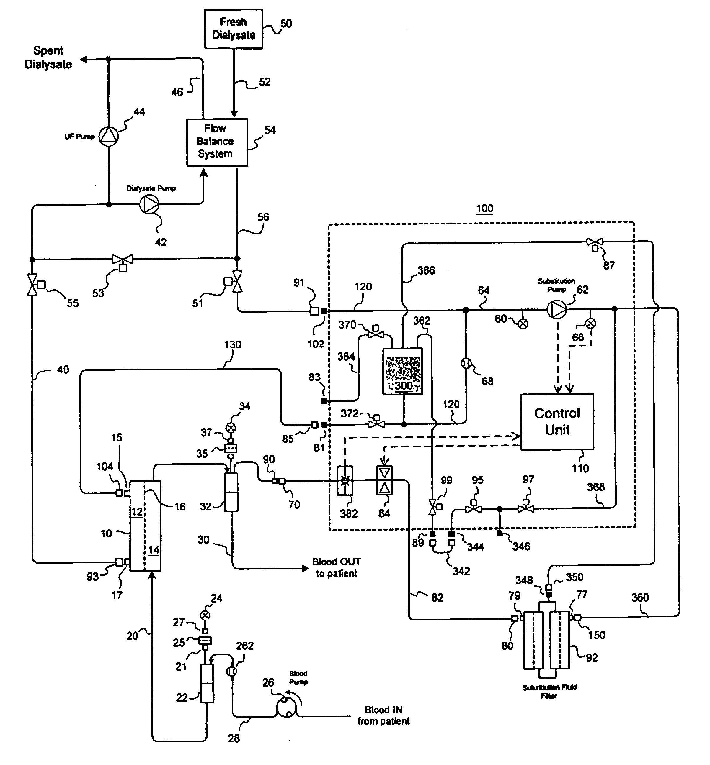
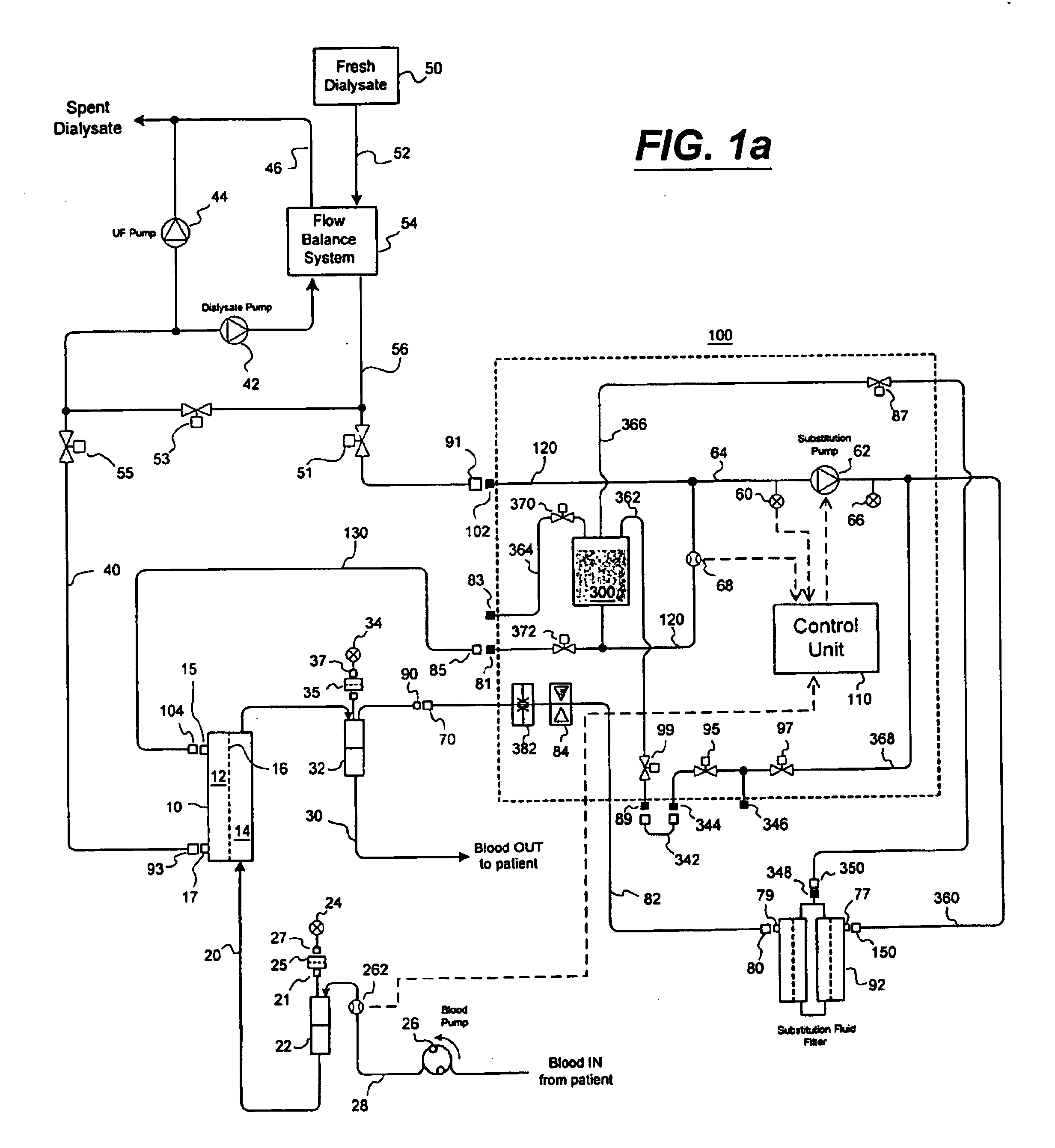
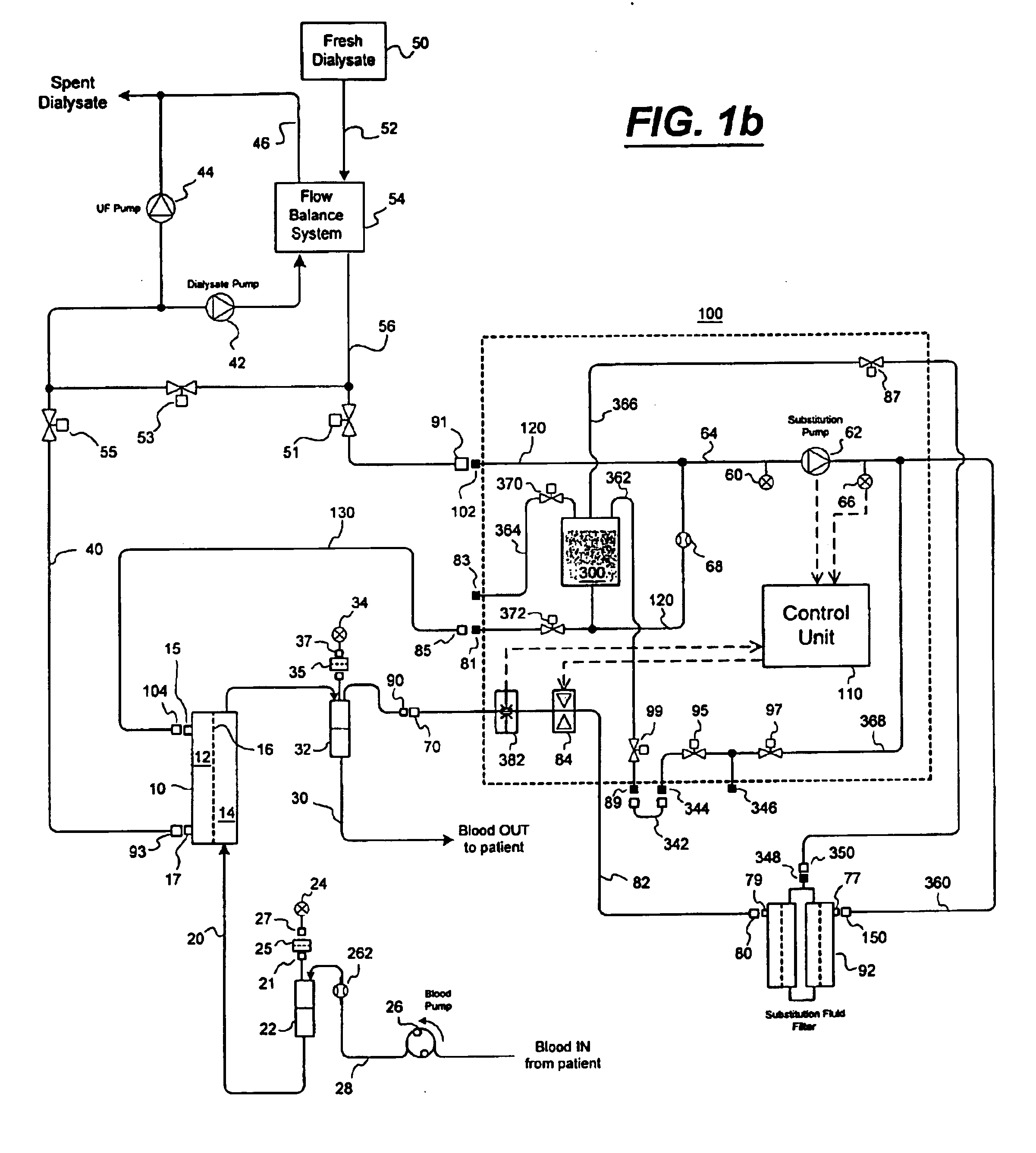
[0007]This invention provides a method and apparatus for a hemodiafiltration delivery module that is used in conjunction with a UF controlled
dialysis machine to enable hemodiafiltration therapy to be performed. The
advantage is that one can fully utilize a current functioning dialysis machine to perform a hemodiafiltration therapy as opposed to
purchasing a completely new machine that offers this capability.
[0008]It is an object of the present invention to overcome safety issues that arise when there is no coordination between dialysis machine events (eg. alarm conditions, mode shifts, etc.) and an externally controlled substitution fluid pump. In particular, it an object of the invention to prevent unsafe or hazardous conditions, such as can occur when the substitution pump continues to pump fluid after the
blood pump on the dialysis machine stops circulating blood through the
extracorporeal circuit or after the dialysis machine stops delivering dialysate fluid to the substitution pump and dialyzer.
[0009]In addition, it is an object of the invention to prevent blood from contaminating the final sterilizing filter (referred to as a substitution fluid filter
cartridge) and thus enable the sterilizing filter to be used multiple times without having to disinfect or replace the sterilizing filter between each treatment. It is also an object of the invention to be able to provide sterile substitution fluid that can be used for priming and blood rinseback as well as providing a fluid bolus to the patient during treatment. A further object of the invention is to provide a method and apparatus that can be rinsed and disinfected either in conjunction with the dialysis machine or independently from the dialysis machine. Additional objects of the invention are to provide a means to detect when the substitution filter becomes plugged, such as by measuring the filter water permeability, and provide a means to detect the integrity of the substitution filter(s) as well as the fluid path of the
diafiltration module. And finally, it is an object of the invention to fully pass the dialysate
stream through at least a first filtering stage of a substitution filter, thereby improving the quality of the dialysate introduced into the dialysate compartment of the dialyzer.
[0012]According to another aspect of the invention, the
diafiltration delivery module prevents blood from backing up into the sterilizing filter. This has the
advantage that the sterilizing filter can be used multiple times for subsequent treatments without having to discard and / or reprocess the sterilizing filter between treatments. In the first embodiment of the invention, this is accomplished by use of solenoid actuated
pinch valve that is positioned on the flexible infusion tubing connected between the sterilizing filter and the
extracorporeal filter. Control of the
pinch valve is such that the valve is only opened when certain conditions are met, such as a minimum pre-filter pressure is achieved. The
pinch valve may be automatically closed whenever an optical blood sensor (located between the pinch valve and the
extracorporeal circuit) detects blood or when a sudden increase in pre-filter pressure is detected to be above a specified threshold value. In a seventh embodiment of the invention, a
check valve is incorporated as part of the infusion
tubing set as a secondary means to prevent blood from backing up into the sterilizing filter. This eliminates the need for the optical blood sensor described in the first embodiment. In an eighth embodiment of the invention, a peristaltic or roller (occluding type) pump is used in place of the pinch valve. This has the advantage of eliminating the need for the pinch valve and thus reducing the number of hardware components used in the
diafiltration delivery module, however, this comes at the expense of requiring a special infusion line containing a pump segment that fits the substitution pump.
[0013]In a third aspect of the invention, it is desired to filter the entire dialysate
stream as a means to improve the quality of dialysate entering the dialysate compartment of the dialyzer (in addition to generating sterile infusion fluid for diafiltration.) In an ninth embodiment of the invention, this is accomplished by running the substitution pump at a higher rate than the
dialysate flow rate so that all the dialysate is filtered through at least a first filter stage of a sterilizing filter. A throttling valve placed in the fluid circuit on the downstream side of the first sterilizing filter is then used to generate a sufficient
back pressure necessary to force the desired amount of substitution fluid through a second or final sterilizing filter. Adjustments to the aperture of the throttling valve may be based on input from a flow meter located on the dialysate
stream leading to the dialyzer. As part of a tenth embodiment of the invention, it is also shown that one can control the rate of substitution fluid used for diafiltration using a
feedback control loop based on flow restrictor devices and pressure inputs instead of the flow meter / throttling valve configuration. This has the distinct advantage in that one does not require use of an expensive flow meter and throttling valve to achieve this dialysate filtering aspect of the invention.
[0016]And finally, in a tenth embodiment of the invention, it is further shown how the diafiltration delivery module may been separated into a treatment module and a reuse / test module. In this embodiment, the treatment module may be used without the reuse / test module when performing diafiltration treatments on the dialysis machine. In order to test the sterilizing filter and reprocess it for subsequent use, however, requires one to connect the reuse / test module to the treatment module to enable the test and disinfect functions to be performed. One advantage of this scheme is that the treatment module can be made much smaller as it contains only those components needed for carrying out the treatment aspects. This important because it is desirable to minimize the amount of space taken up by the diafiltration delivery module when connected to the dialysis machine. Another advantage has to do with preventing hazardous conditions associated with accidentally performing test / disinfect functions during treatment. For example, with separable modules, it would be impossible to invoke a hazardous disinfect process without the reuse / test module being connected to the treatment module.

