Solder ball assembly, a method for its manufacture, and a method of forming solder bumps

a technology of solder ball and assembly, which is applied in the manufacture of printed circuits, basic electric elements, printed circuit assembling, etc., can solve the problems of reflowing solder ball and forming solder bumps on the electrodes, and achieve the effect of efficient formation

Inactive Publication Date: 2005-07-19
SENJU METAL IND CO LTD
View PDF9 Cites 27 Cited by
  • Summary
  • Abstract
  • Description
  • Claims
  • Application Information

AI Technical Summary

Benefits of technology

[0007]The present invention provides a solder ball assembly which enables solder balls to be efficiently formed on an electrode pattern on a substrate, and even one having an extremely fine pitch of 200 μm or less. The present invention also provides a method of manufacturing the solder ball assembly and a method of forming solder bumps using the solder ball assembly.
[0008]The present inventors founds that solder balls can be easily arranged in a desired pattern corresponding to a pattern of electrodes on which solder bumps are to be formed by inserting the solder balls into holes formed in a mask and then fixing the solder balls in the holes with a fixing agent. The fixing agent enables the mask to be handled without the solder balls falling out of the holes. The mask can be placed atop a substrate with each of the holes in the mask (and with each of the solder balls which are disposed in the holes) aligned with a corresponding electrode on the substrate. If the mask is heated in this state, the heating causes the fixing agent to flow and release the solder balls from the mask. Heating also causes the solder balls to reflow and form solder bumps atop the electrodes. After the solder bumps have solidified atop the electrodes, the mask can be removed from the substrate.
[0009]The mask can be formed very easily and inexpensively, so changes in the pattern of electrodes on a substrate can be readily accommodated by forming a new mask having a pattern of holes corresponding to the new electrode pattern.
[0013]Inserting the solder balls into the holes in the mask may be facilitated by applying suction to the second end of each hole while inserting the solder balls into the holes.

Problems solved by technology

Heating also causes the solder balls to reflow and form solder bumps atop the electrodes.

Method used


Image

  • Solder ball assembly, a method for its manufacture, and a method of forming solder bumps
  • Solder ball assembly, a method for its manufacture, and a method of forming solder bumps
  • Solder ball assembly, a method for its manufacture, and a method of forming solder bumps

Examples


example 1

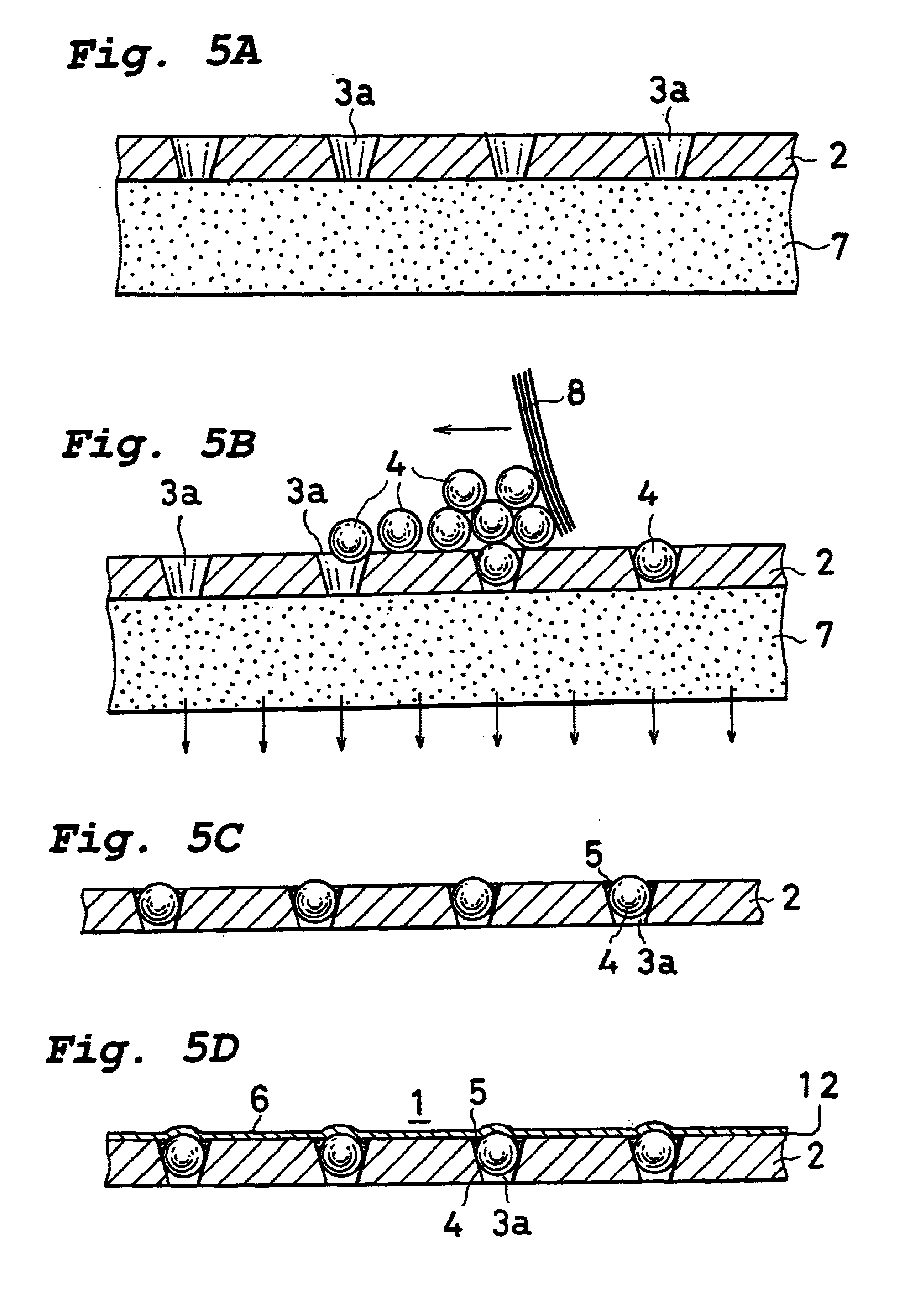
[0067]In this example, a protective sheet having an adhesive layer is attached to the first side of a mask. The protective sheet also exerts a fluxing action.

[0068]A protective sheet having a fluxing action was prepared in the following manner.

[0069]A mixture having a rosin and an organic acid as main fluxing components was dissolved in isopropyl alcohol and coated on a polyester sheet with a thickness of 25 μm to form a coating with a dried thickness of 30 μm. The coated surface exhibited a slight stickiness at room temperature, and the stickiness further increased at 80° C.

[0070]A mask having a plurality of solder balls disposed in each of the holes provided therein was prepared in the following manner.

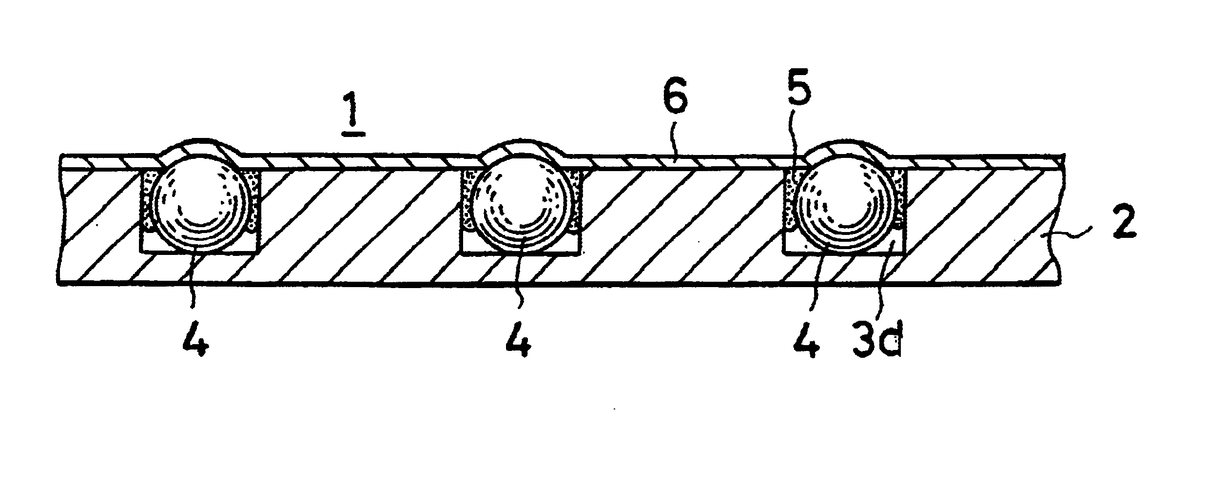
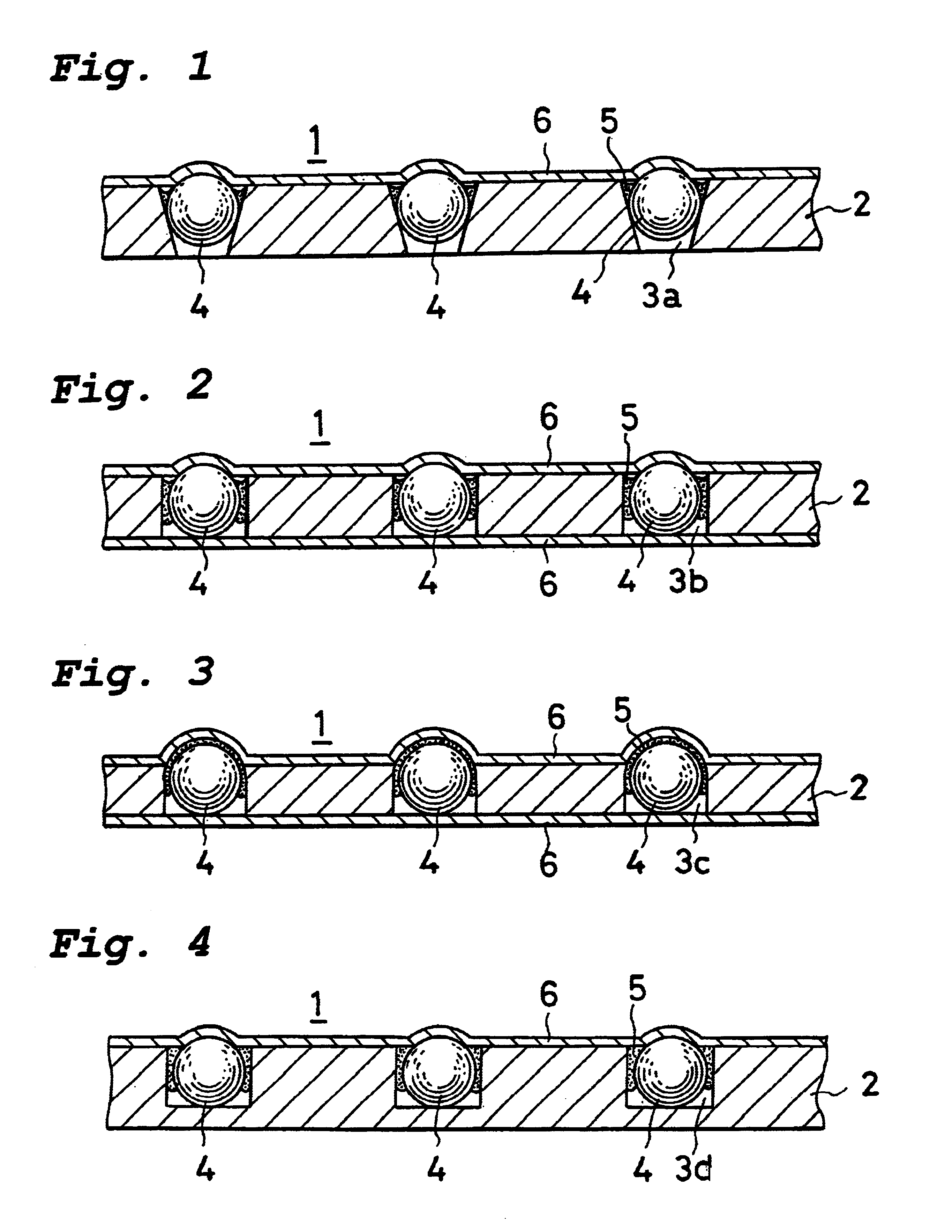
[0071]Ten thousand tapered holes each having a diameter of 120 μm at its first end and a diameter of 50 μm at its second end and having a pitch of 200 μm were formed by laser beam machining in a mask comprising a polyester sheet with a thickness of 125 μm. The mask was placed on a s...

example 2

[0074]A commercially available polypropylene sheet with a thickness of 25 μm which had been coated with an acrylic adhesive was applied to the second side of the mask of Example 1 as a lower protective sheet. The upper and lower protective sheets together isolated the solder balls in the mask from air, so surface deterioration of the solder balls by oxygen could be slowed.


PUM


Abstract

A solder ball assembly includes a mask having first and second sides and a plurality of holes formed therein. Each hole has a first end opening onto the first side of the mask and a second end. A plurality of solder balls are disposed in the holes, and a fixing agent secures the solder balls in the holes. A protective sheet may be attached to one or both sides of the mask to cover the ends of the holes.

Description

BACKGROUND OF THE INVENTION[0001]1. Field of the Invention[0002]This invention relates to a ball assembly for use in arranging solder balls or other types of balls in a prescribed pattern in preparation for forming the balls into solder bumps. It also relates to a method for manufacturing a ball assembly, and to a method of forming solder bumps using the ball assembly.[0003]2. Description of the Related Art[0004]One method of soldering an electronic part to a substrate employs solder bumps, which are previously formed on the electrodes of the electronic part and / or the electrodes of the substrate.[0005]Various methods have been proposed in the past for forming solder bumps, such as the solder paste method, the solder ball method, and the plating method. Each of these methods has its advantages and disadvantages. The solder ball method is advantageous in that the amount of solder which is applied to an electrode can be accurately controlled, and it is relatively economical. In carryi...

Claims


Application Information

Patent Timeline
Patent Type & Authority Patents(United States)
IPC IPC(8): H01L21/48H01L21/02H05K3/34H01L21/60
CPCH01L21/4853H01L24/11H05K3/3478H01L2224/13099H01L2924/01005H01L2924/01015H01L2924/01029H01L2924/01033H01L2924/01047H01L2924/01078H01L2924/01082H01L2924/01322H01L2924/09701H05K3/3489H05K2203/0113H05K2203/0338H05K2203/041H05K2203/082H01L2924/01006H01L2924/014H01L2224/11334H01L2224/05568H01L2224/05573H01L2924/00014H01L2924/12042H01L2924/00H01L2224/05599
Inventor KURAMOTO, TAKEOTSURUTA, KAICHI
Owner SENJU METAL IND CO LTD
Why Eureka
Try Eureka