
RF antenna coupling structure

a technology of coupling structure and antenna, applied in the field of communication system, can solve the problems of large energy loss, large noise figure of balun, and recent attempts to integrate balun onto radio frequency integrated circuit,

Inactive Publication Date: 2005-07-19
AVAGO TECH WIRELESS IP SINGAPORE PTE
View PDF8 Cites 185 Cited by
  • Summary
  • Abstract
  • Description
  • Claims
  • Application Information

AI Technical Summary

Benefits of technology

The solution provides improved noise performance, energy efficiency, and impedance matching for both power amplifiers and low noise amplifiers, achieving a symmetrical balun antenna coupling structure that meets the operational requirements of both components.

Problems solved by technology

Recent attempts to integrate a balun onto a radio frequency integrated circuit have had limited success.
For example, parallel winding, inter-wound winding, overlay winding, single planar, square wave winding, and concentrical spiral winding on-chip baluns have been tried with limited success.
Each of these on-chip baluns suffers from one or more of low quality factor, (which causes the balun to have a relatively large noise figure and large energy loss); too low of a coupling coefficient (which results in the inductance value of the balun not significantly dominating the parasitic capacitance making impedance matching more complex); asymmetrical geometry (which results in degradation of differential signals); and a relatively high impedance ground connection at the operating frequency.
Other problems exist for RFICs that include on-chip baluns.
A PA balun, however, is required to support large currents, which requires a large track width of the transformer windings.

Method used


Image

  • RF antenna coupling structure
  • RF antenna coupling structure
  • RF antenna coupling structure

Examples


Embodiment Construction

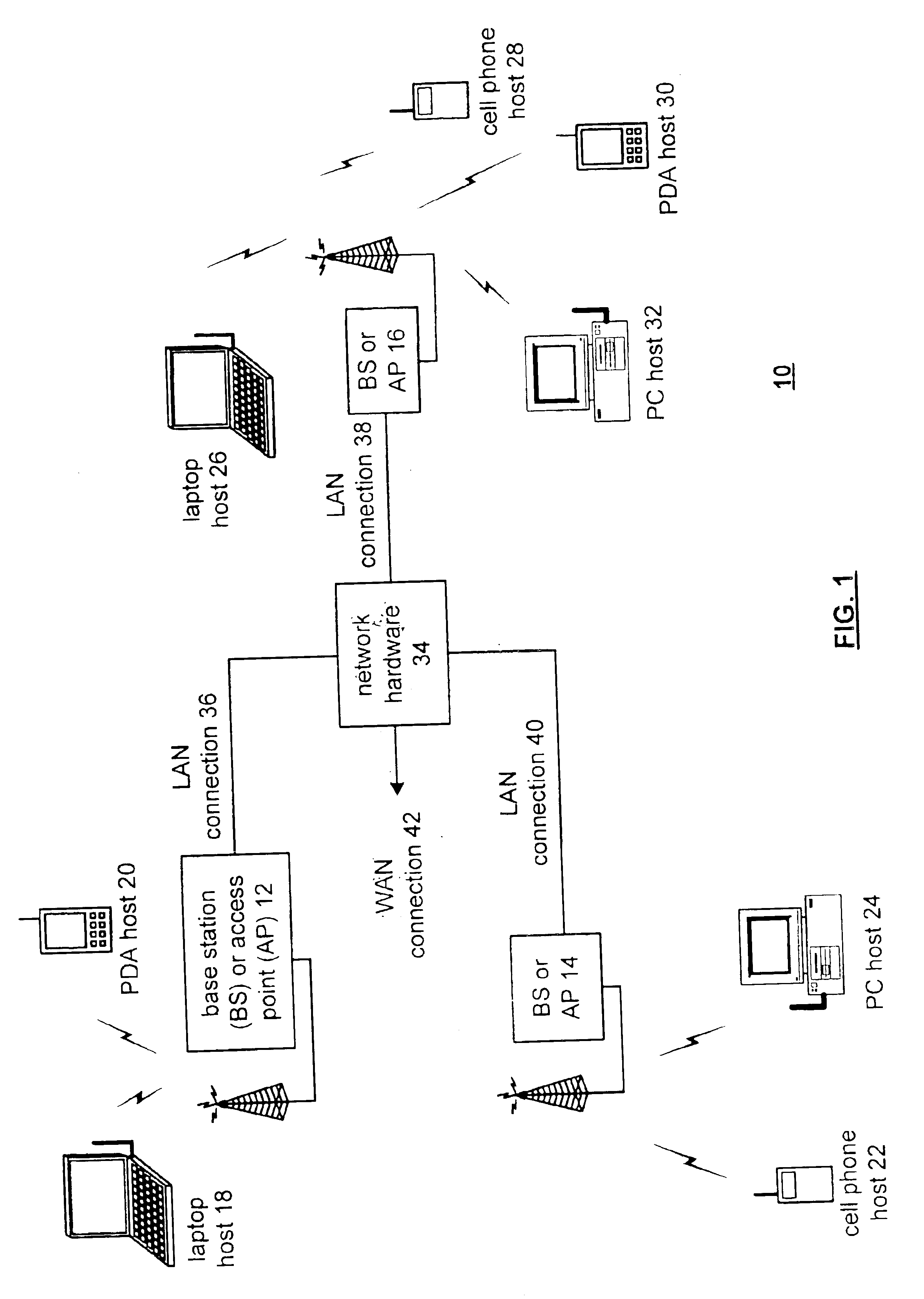
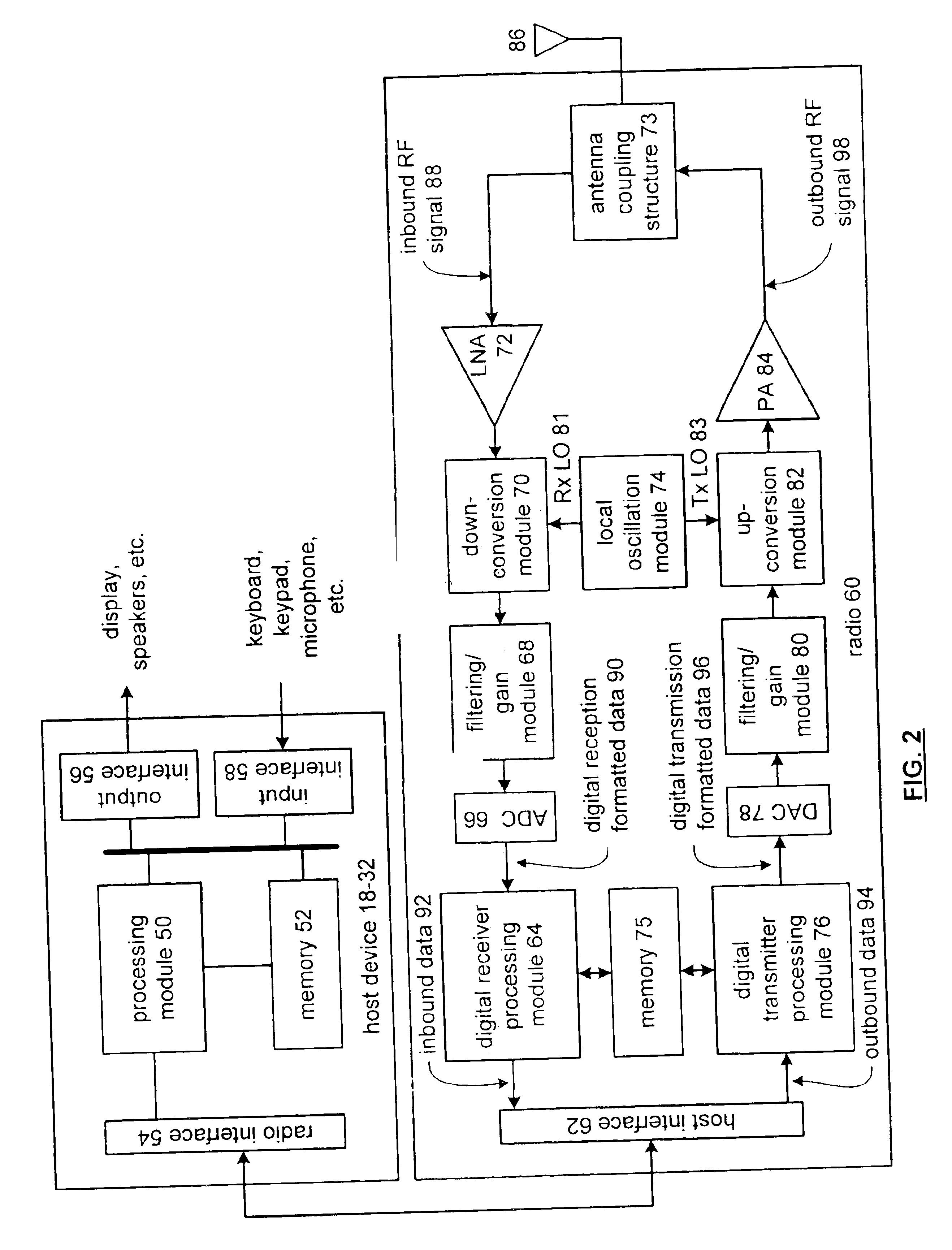
[0016]FIG. 1 illustrates a schematic block diagram of a communication system 10 that includes a plurality of base stations and / or access points 12-16, a plurality of wireless communication devices 18-32 and a network hardware component 34. The wireless communication devices 18-32 may be laptop host computers 18 and 26, personal digital assistant hosts 20 and 30, personal computer hosts 24 and 32 and / or cellular telephone hosts 22 and 28. The details of the wireless communication devices will be described in greater detail with reference to FIG. 2.

[0017]The base stations or access points 12 are operably coupled to the network hardware 34 via local area network connections 36, 38 and 40. The network hardware 34, which may be a router, switch, bridge, modem, system controller, et cetera, provides a wide area network connection 42 for the communication system 10. Each of the base stations or access points 12-16 has an associated antenna or antenna array to communicate with the wireless ...


PUM


Abstract

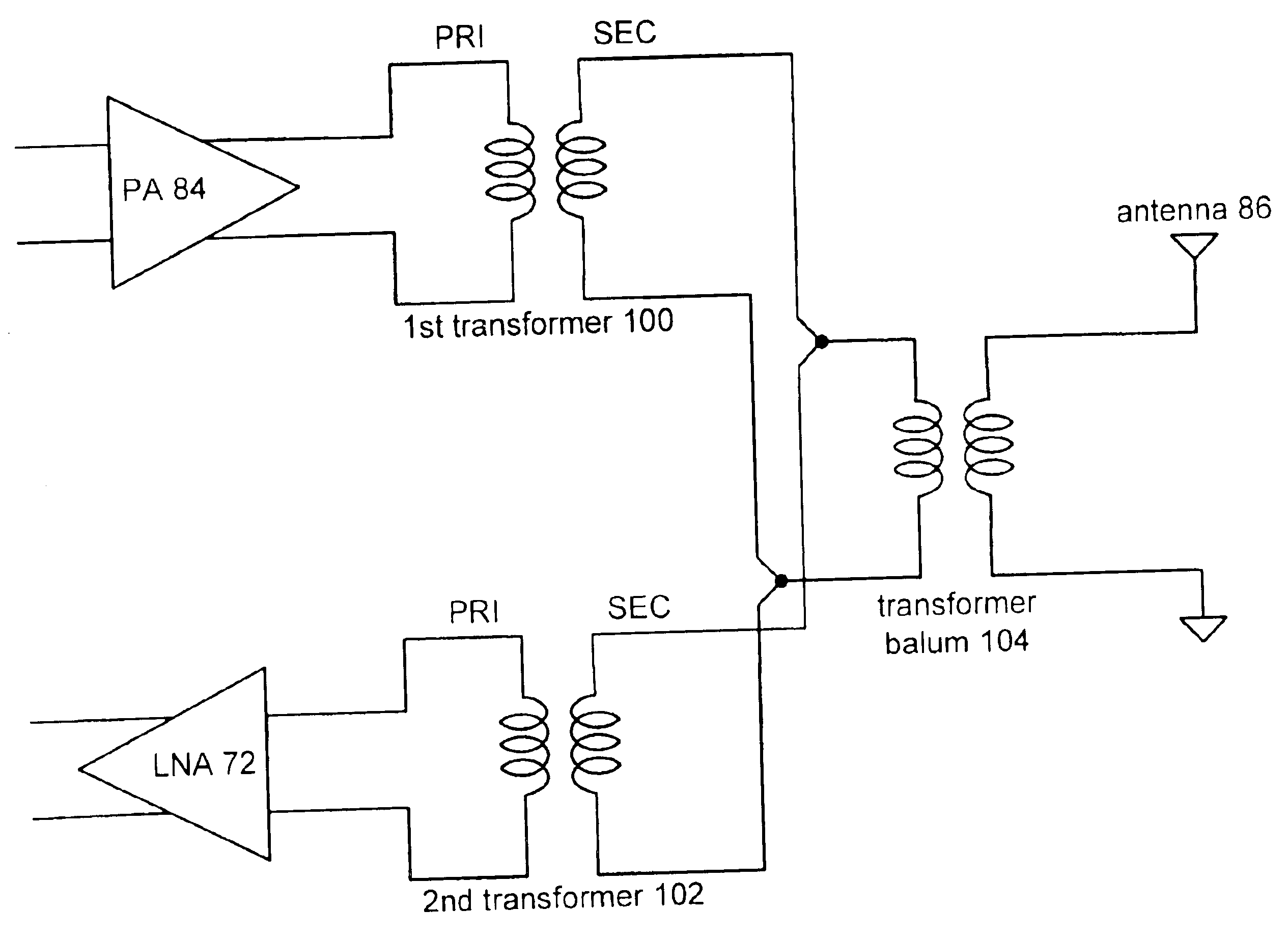
An RF antenna coupling structure includes a first transformer, a second transformer, and a transformer balun. The first transformer includes a primary winding and a secondary winding, wherein the primary winding of the first transformer is operably coupled to a power amplifier, and wherein the secondary winding of the first transformer has a desired output impedance corresponding to the operational needs of the power amplifier. The second transformer includes a primary winding and a secondary winding, wherein the primary winding of the second transformer is operably coupled to a low noise amplifier, and wherein the secondary winding of the second transformer has a desired output impedance corresponding to the needs of the low noise amplifier. The transformer balun includes a differential winding and a single-ended winding, wherein the differential winding is operably coupled to the secondary windings of the first and second transformers and the single-ended winding is operably coupled to an antenna.

Description

BACKGROUND OF THE INVENTION[0001]1. Technical Field of the Invention[0002]This invention relates generally to communication systems and, more particularly, to radio receivers and transmitters used within such communication systems.[0003]2. Description of Related Art[0004]Communication systems are known to support wireless and wire-lined communications between wireless and / or wire-lined communication devices. Such communication systems range from national and / or international cellular telephone systems to the Internet to point-to-point in-home wireless networks. Each type of communication system is constructed, and hence operates, in accordance with one or more communication standards. For instance, wireless communication systems may operate in accordance with one or more standards including, but not limited to, IEEE 802.11, Bluetooth, advanced mobile phone services (AMPS), digital AMPS, global system for mobile communications (GSM), code division multiple access (CDMA), local multi-...

Claims


Application Information

Patent Timeline
Patent Type & Authority Patents(United States)
IPC IPC(8): H04B1/18
CPCH04B1/18
Inventor ROFOUGARAN, AHMADREZA REZA
Owner AVAGO TECH WIRELESS IP SINGAPORE PTE
Learn More