Electrostatic pellicle system for a mask

a technology of electromagnetic pellicle and mask, which is applied in the field of electromagnetic pellicle system for mask, can solve the problems of few materials being sufficiently transparent or durabl

Inactive Publication Date: 2005-07-26
INTEL CORP
View PDF3 Cites 10 Cited by
  • Summary
  • Abstract
  • Description
  • Claims
  • Application Information

AI Technical Summary

Problems solved by technology

However, very few materials are sufficiently transparent or durable whe

Method used


Image

  • Electrostatic pellicle system for a mask
  • Electrostatic pellicle system for a mask
  • Electrostatic pellicle system for a mask

Examples


Embodiment Construction

[0013]In the following description, numerous particular details, such as specific materials, dimensions, and processes, are set forth in order to provide a thorough understanding of the present invention. However, one skilled in the art will realize that the invention may be practiced without these particular details. In other instances, well-known semiconductor equipment and processes have not been described in particular detail so as to avoid obscuring the present invention.

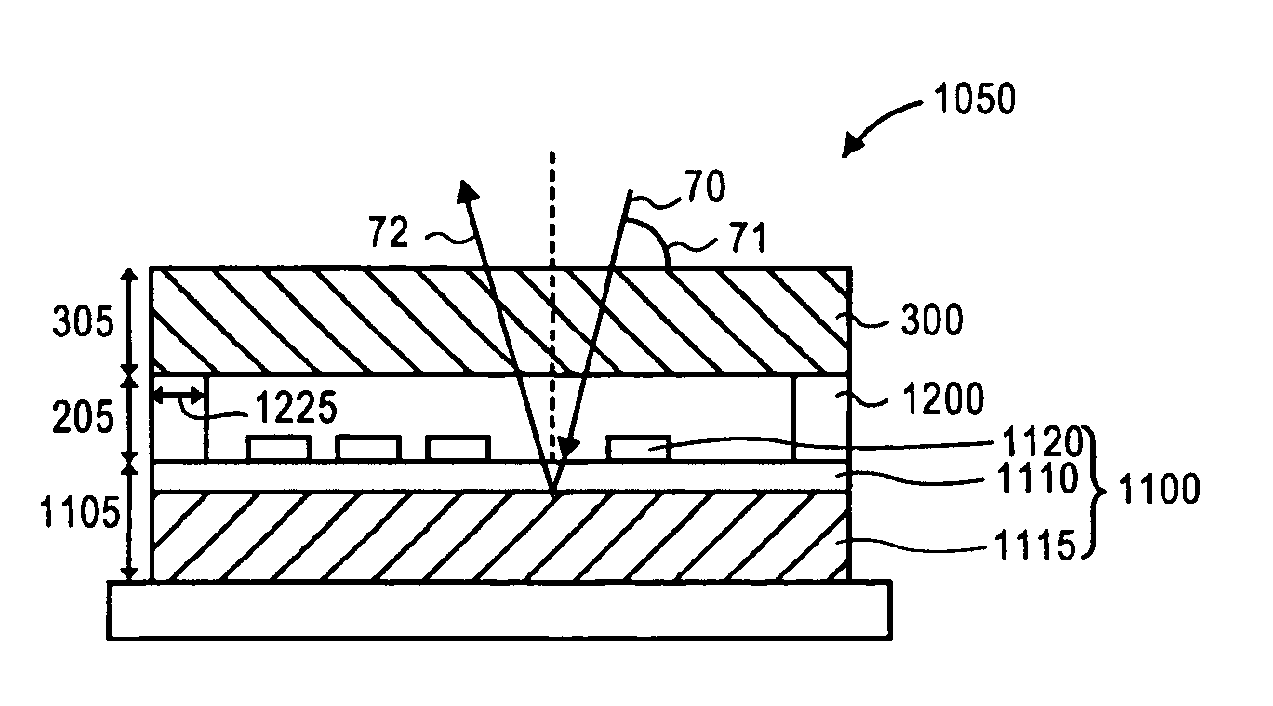
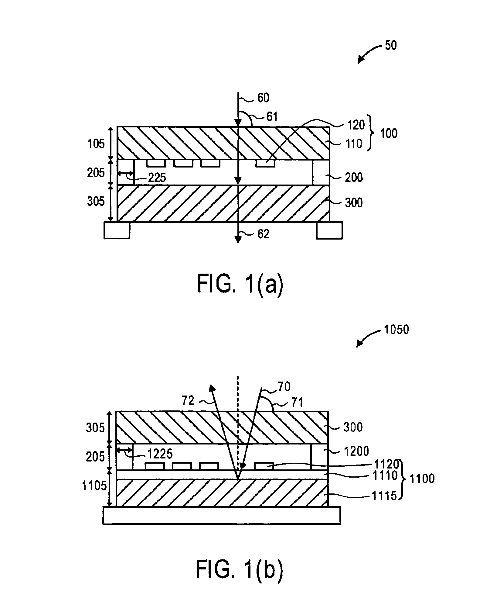
[0014]Contamination must be kept away from a path of exposure radiation in an exposure tool, such as a stepper, to ensure fidelity of a pattern transfer from a mask to a photoresist coated on a wafer. The mask may be transmissive or reflective. The path of exposure radiation in the stepper includes a vicinity of the mask. The present invention comprises an apparatus for and a method of keeping contamination away from the vicinity of the mask during exposure. The apparatus may include an electrostatic pellicle s...


PUM


Abstract

The present invention describes an apparatus comprising a mask; a pellicle spacer, the pellicle spacer attached to the mask; and an electrostatic pellicle system, the electrostatic pellicle system attached to the pellicle spacer.
The present invention further describes a method of keeping contaminants away from a vicinity of a mask during exposure, the contaminants including an uncharged or neutral particle, a positively-charged particle, or a negatively-charged particle, comprising: inducing a positive or negative charge on the uncharged or neutral particle; attracting the positively-charged particle with a negatively-charged electric field; and attracting the negatively-charged particle with a positively-charged electric field.

Description

[0001]This is a Continuation application of Ser. No.: 10 / 112,454, filed Mar. 28, 2002, now U.S. Pat. No.: 6,803,159.FIELD OF THE INVENTION[0002]The present invention relates generally to the field of semiconductor integrated circuit (IC) manufacturing, and, more specifically, to an apparatus for and a method of keeping contaminants away from the vicinity of a mask during exposure.BACKGROUND OF THE INVENTION[0003]The manufacturing of IC devices involves the sequential processing of a semiconductor wafer to add or remove various layers of materials. The critical layers define features in the IC devices that possess tighter groundrules, such as those for isolation, gate, contact, and first metal, while the non-critical layers define the remaining features.[0004]The process of photolithography is performed to pattern the layers on the wafer. Initially, the wafer is covered with photoresist or other material that is sensitive to light energy. Then, an imaging tool, such as a stepper, ali...

Claims


Application Information

Patent Timeline
IPC IPC(8): G03F1/14G03F1/24G03F1/62
CPCB82Y10/00B82Y40/00G03F1/24G03F1/62
Inventor ENLOE, DAN
Owner INTEL CORP
Why Eureka
Try Eureka