Digital optical beam profiler

a digital and optical beam technology, applied in the field of optical beam profile measurement systems, can solve the problems of reducing the repeatability of profiler measurement, adding cost and complexity to the optical beam profiler, and hysteresis and motion sensitivity limits, so as to achieve low cost, low electrical analog/digital drive control, and low cost

Inactive Publication Date: 2005-07-26
NUONICS
View PDF2 Cites 9 Cited by
  • Summary
  • Abstract
  • Description
  • Claims
  • Application Information

AI Technical Summary

Benefits of technology

[0008]It is an object of this invention to introduce a digitally controlled optical beam profiler that uses a spatial light modulator. In an aspect of the invention, the spatial light modulator includes an array of 2-D small tilt micromirrors. This small tilt micromirror device is based on the mature microelectromechanical system (MEMS) technology that offers low cost, compact mechanical elements with low electrical analog / digital drive control via the use of low cost batch fabrication techniques similar to semiconductor electronic chip production methods. The profiler incorporates the basic principles of a 2-D photodetector array and mechanical scanning techniques via a 2-D MEMS device, leading to the implementation of an all-digital control profiler that has the ability to digitally replicate the moving mechanical elements of conventional optical profilers. In addition, cooperation between the array of 2-D small tilt micromirrors and a high sensitivity photodetector inherently forms the 2-D photodetector array-based optical beam profiler. Other advantages of exploiting a 2-D micromirror array are low polarization sensitivity, broadband wavelength operation, profiler fault-tolerance to individual mirror failure, and high measurement repeatability. In general, any 2-D multi-pixel transmissive / reflective / absorptive device can be used in the proposed optical beam profiler.

Problems solved by technology

However, some limiting factors such as wavelength sensitivity in multiphoton ionization method, the need of a dilute solution in fluorescence correlation spectroscopy technique, and the requirement to use a high power pulse laser for thermal graphic techniques are the reasons that have propelled the simpler moving mechanical element and the 2-D photodiode array approaches to being commercially dominant.
These common mechanical scanning methods use scanning elements that are moved in an analog fashion and therefore require precise analog voltage control that adds cost and complexity to the optical beam profilers.
Furthermore, hysteresis and motion sensitivity limits in mechanical elements reduce profiler measurement repeatability.

Method used


Image

  • Digital optical beam profiler
  • Digital optical beam profiler
  • Digital optical beam profiler

Examples


Embodiment Construction

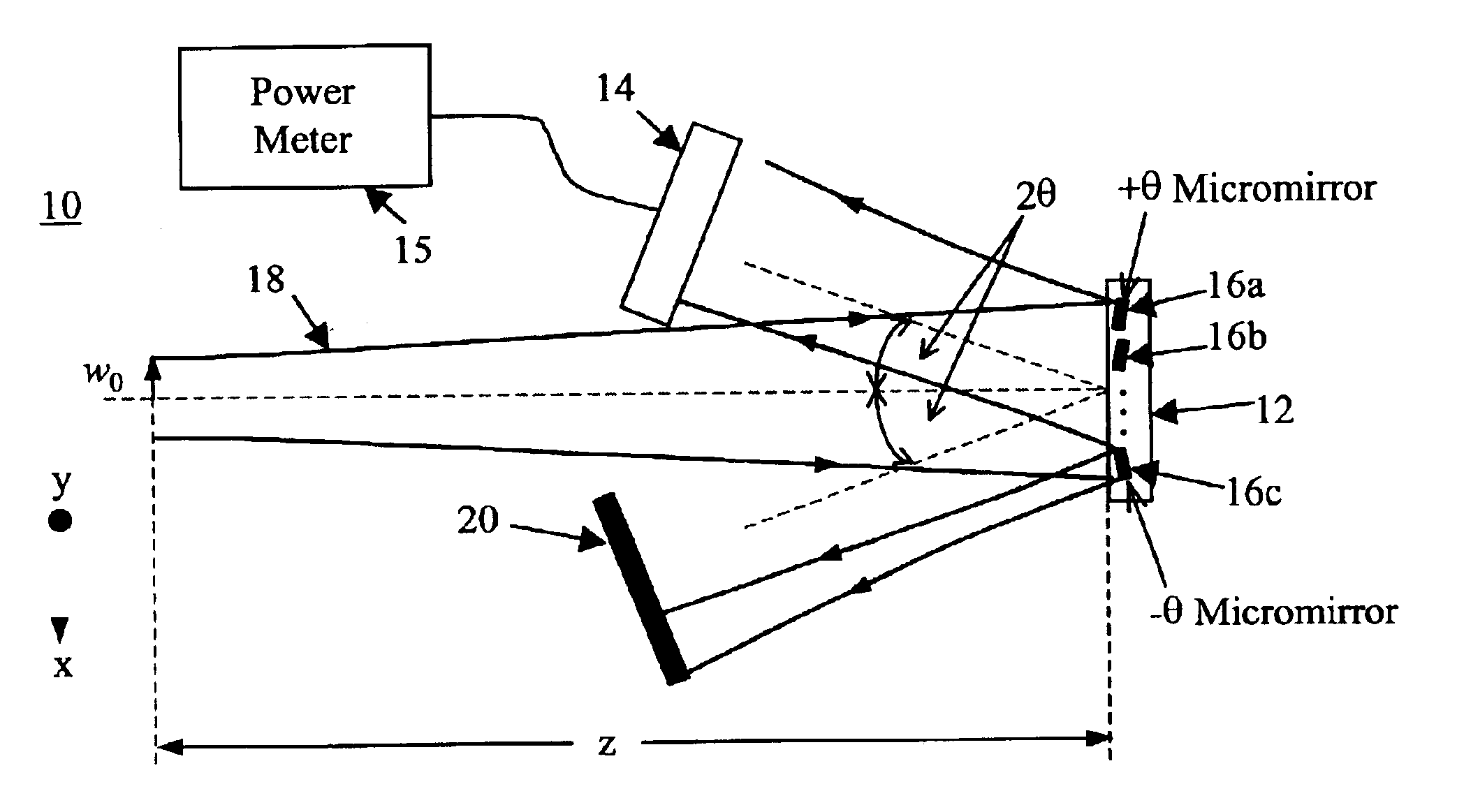
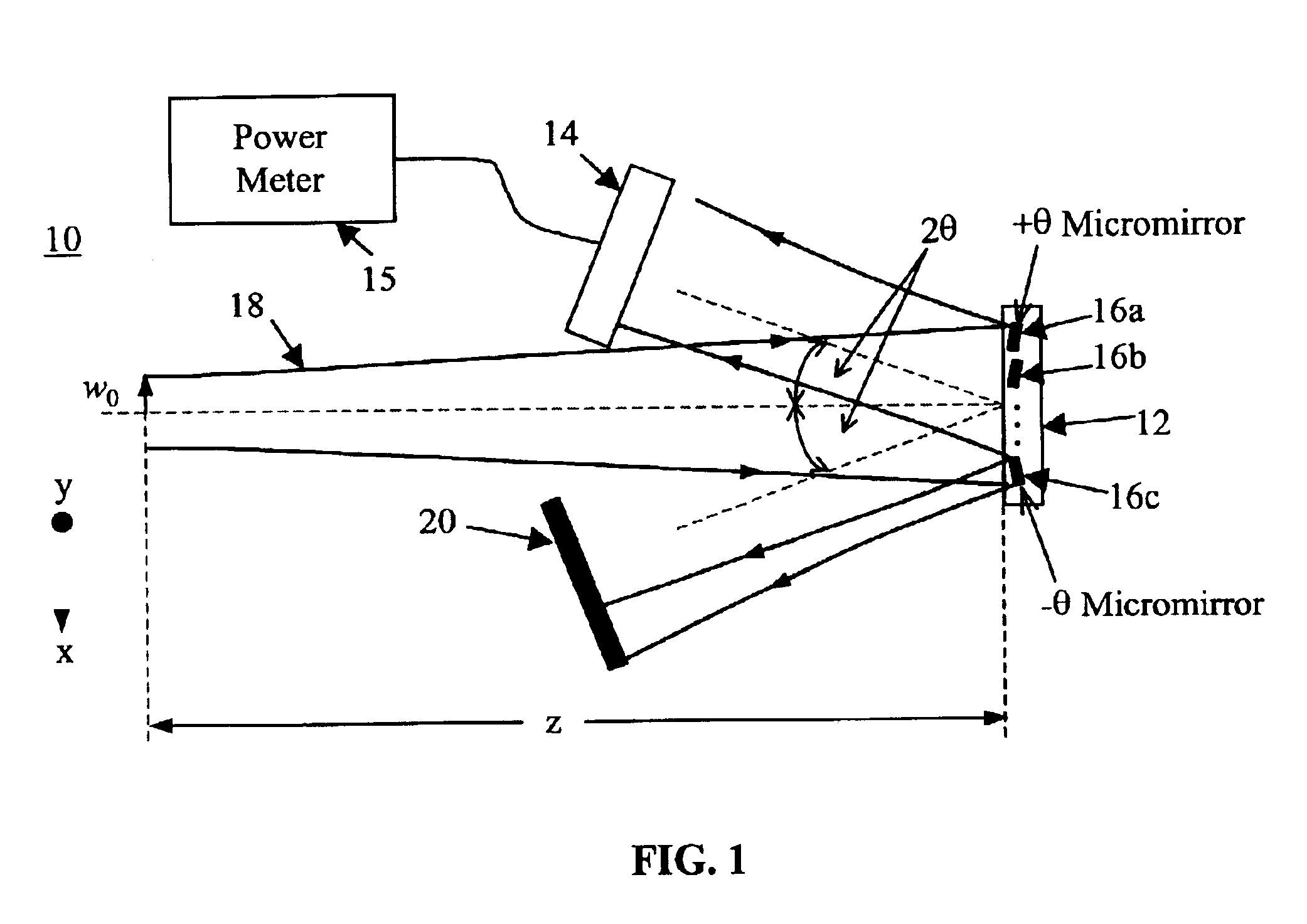
[0013]In general, the invention includes a programmable spatial light modulator for selectively directing light from an incident optical beam and a photodetector for detecting an intensity of the light directed by the spatial light modulator. The basic structure of an embodiment implemented as a digitally controlled MEMS-based optical beam profiler 10 is shown in FIG. 1. In an aspect of the invention, the beam profiler 10 uses a 2-D small tilt micromirror device 12 and a 2-D photodetector 14. Each micromirror 16a, 16b, and 16c, of the micromirror device 12 may have two states of operation: +θ and −θ mirror positions. As seen in FIG. 1, when the desired micromirrors are set to +θ position (for example, as shown by the angular position of micromirrors 16a and 16b) the corresponding part of the optical beam 18 is reflected to the photodetector 14 and the power of detected light can be measured by a power meter 15. In another aspect, the optical beam 18 can be directed to an absorber 20...


PUM


Abstract

An optical beam profiler using a spatial light modulator and photodetector. In an embodiment, the spatial light modulator is a two-dimensional (2-D) small tilt digital micromirror device. The profiler features fast speed, digital controls, low polarization sensitivity, and high measurement repeatability. The 2-D multi-pixel device-based profiler allows the use of several beam profile measurement concepts including moving knife edge, scanning slit, moving pinhole, variable aperture, and 2-D photodiode array. The proposed digital optical beam profiler can be implemented with any type of digitally operated 2-D spatial light modulator device such as using liquid crystals, magneto-optics, multiple quantum wells, electro-optic polymers, and photonic crystals.

Description

SPECIFIC DATA RELATED TO INVENTION[0001]This application claims the benefit of U.S. Provisional Patent Application No. 60 / 355,658 filed Feb. 8, 2002, and U.S. Provisional Patent Application No. 60 / 408,830 filed Sep. 6, 2002, incorporated herein by reference.BACKGROUND OF THE INVENTION[0002]1. Field of the Invention[0003]The present invention is generally related to optical beam profile measurement systems, and, specifically, to a digital optical beam profiler using a spatial light modulator.[0004]2. Related Art[0005]Since the invention of laser in the 1960s, lasers have been used extensively in a variety of applications ranging from laser research, optical communications, and material processing to optical metrology. In these applications, it is very important to know the parameters that can describe the laser beam. Optical beam radius is one of these parameters and it is defined as the distance between the maximum optical power or intensity point of the optical beam and the positio...

Claims


Application Information

Patent Timeline
Patent Type & Authority Patents(United States)
IPC IPC(8): G02B26/08G01J1/42G02B26/02G01J1/04
CPCG01J1/04G01J1/0414G01J1/4257G02B26/02G02B26/0841
Inventor RIZA, NABEEL AGHA
Owner NUONICS
Why Eureka
Try Eureka