Metal foil/scrim flashings

a technology of metal foil and scrim flashing, which is applied in the field of flashing systems, can solve the problems of insufficient development of pressure-sensitive hot melt adhesives needed for peel-and-stick applications, insufficient adhesive quality for rough masonry block surfaces, and insufficient filling of pressure-sensitive products, etc., and achieve the effect of enhancing tear and puncture resistan

Inactive Publication Date: 2005-08-16
HOHMANN & BARNARD INC
View PDF16 Cites 25 Cited by
  • Summary
  • Abstract
  • Description
  • Claims
  • Application Information

AI Technical Summary

Benefits of technology

[0044]It is a feature of the present invention that the hot melt adhesive hereof is compatible with flashing membranes containing ketone ethylene ester and meets industry flammability standards.
[0045]It is another feature of the present invention that the polymeric membrane hereof is highly, ultra-violet resistant and the membrane includes an embedded woven or non-woven fiber layer to enhance tear and puncture resistance.
[0046]It is yet another feature of the present invention that the termination bar has a foam layer thereon for sealing upon installation and obviate the use of sealants and caulks during the installation of the flashing system.

Problems solved by technology

At that time the technology of pressure-sensitive hot melt adhesives needed for peel-and-stick applications was insufficiently developed.
Some critics indicated that the adhesive quality was insufficient for the rough masonry block surfaces.
Because of the presence of plasticizers, others were apprehensive about the available hot melt adhesives meeting the requisite fire retardancy standards.
However, these filled pressure-sensitive products had disadvantages, such as application problems, phase separation, toxicity, and reduced adhesion upon activation.
While, under ideal circumstances, these peel-and-stick materials were easy to apply, the patent literature indicates that these materials did not conform well to irregular surfaces.
Thus, the prior art bitumens used to secure these flashing materials to masonry walls often lacked the tackiness to bond tightly and durably to the wall surfaces.
On occasion, when circumstances were not ideal, the bitumenous materials drooled marring the aesthetics of the brick veneer.
Although the rubberized asphalt virtually eliminated the possibility of non-adhered areas, the Copper Aqua Flash membrane still had some of the previously described disadvantages of a bitumen-based flashing system.
Despite these early efforts, developing the right combination of materials and methods for flashing cavity walls in a fast and efficient manner has proved elusive.
In addition to the above described technical problems, because there is frequently a delay in erecting the inner wythe and the outer wythe, the flashing installed in the inner wythe is often exposed to substantial ultra-violet radiation.
Here, in situ construction is both labor intensive and requires special equipment for installation.

Method used


Image

  • Metal foil/scrim flashings
  • Metal foil/scrim flashings
  • Metal foil/scrim flashings

Examples


first embodiment

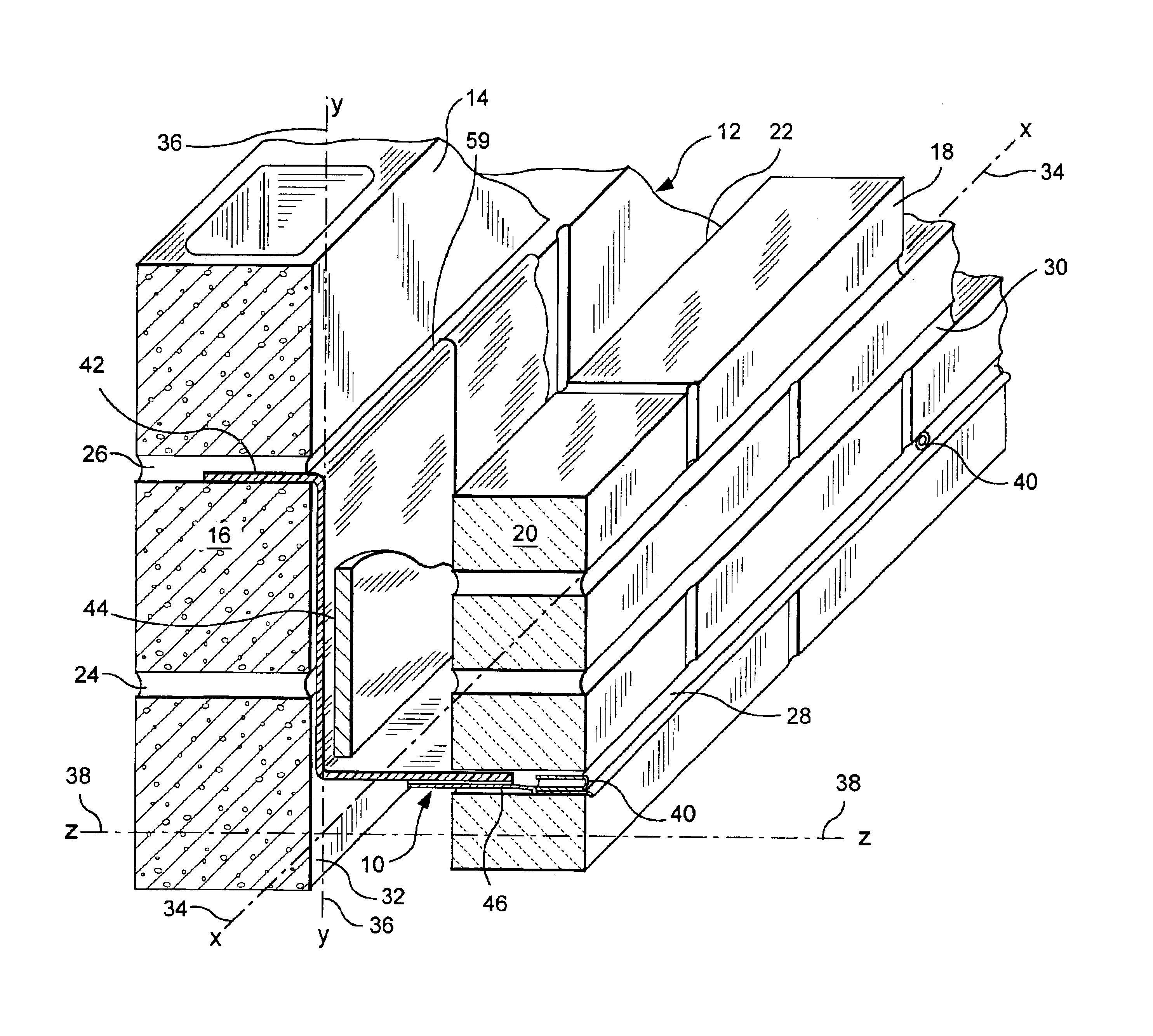
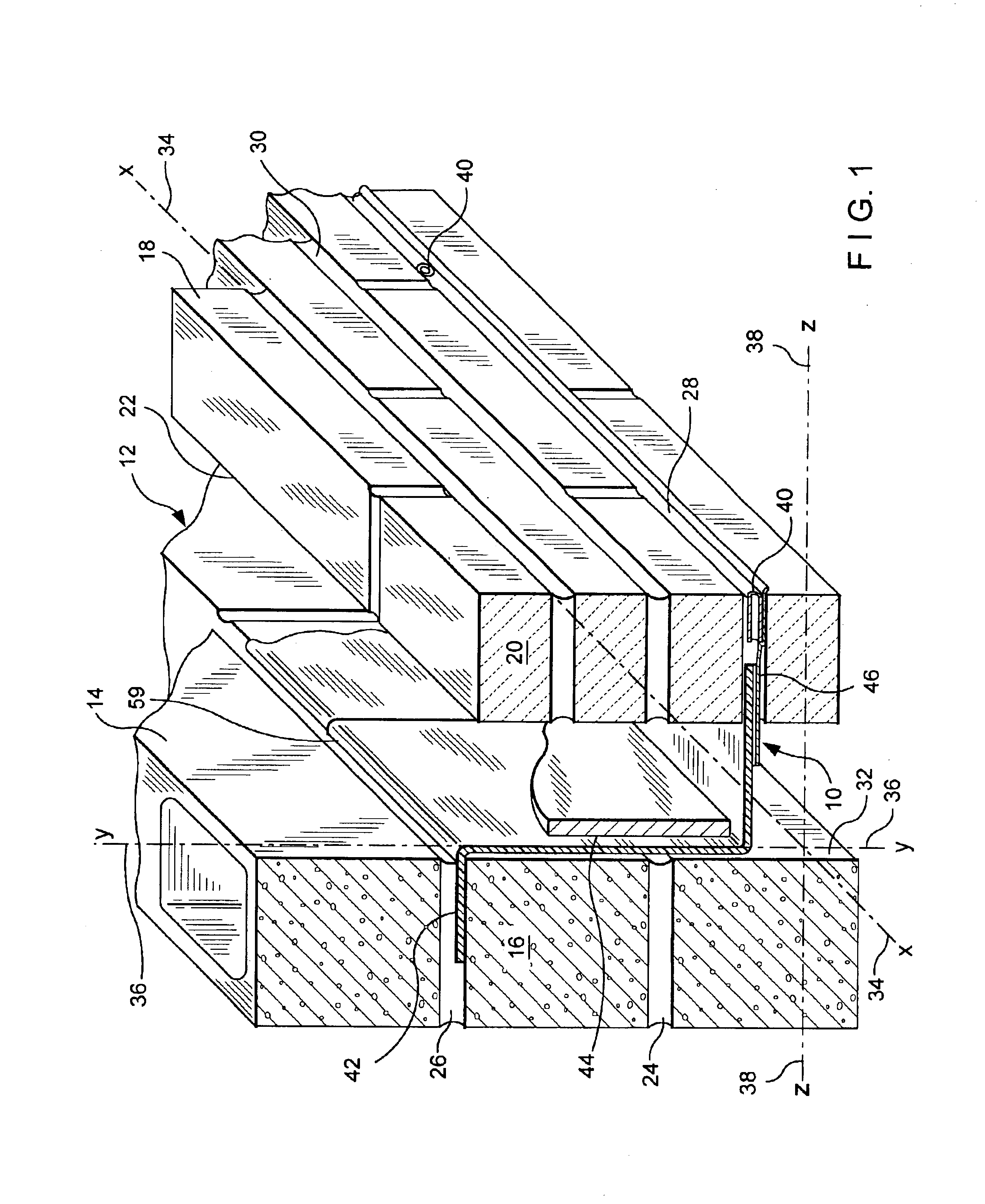
[0060]Referring now to FIGS. 1 through 3, this invention in which a masonry flashing system, referred to generally by the reference designator 10, is shown. In this embodiment, a cavity wall structure 12 is shown having an inner wythe 14 of masonry blocks 16 and an outer wythe 18 of facing brick 20. Between the inner wythe 14 and the outer wythe 18, a cavity 22 is formed. Successive bed joints 24 and 26 are formed between courses of blocks 16 and the joints are substantially planar and horizontally disposed. Also, successive bed joints 28 and 30 are formed between courses of bricks 20 and the joints are substantially planar and horizontally disposed. For the through-wall flashing installation of this embodiment bed joint 26 and bed joint 28 are employed.

[0061]For purposes of this discussion, the exterior surface 32 of the interior wythe 14 contains a horizontal line or x-axis 34 and an intersecting vertical line or y-axis 36. A horizontal line or z-axis 38 also passes through the co...

third embodiment

[0106]As the metal foil / scrim flashing of the third embodiment is not precoated with pressure activated adhesives, the mounting is accomplished utilizing termination bars, described in the patent applications related hereto. The joints, either butt or lap, are sealed in the field with sealing tape or standard mystics.

[0107]Because of environmental and flammability concerns with traditional solvent-based adhesives and an invested position in bitumen-containing materials, the building construction industry has been slow to adopt hot melt adhesive compositions for masonry flashing applications. Now, with the recent advances in hot melt adhesives technology incorporated into the above application advantages over solvent-based or bitumen systems are created hereby. Thus, because the metal / foil scrim membranes described above have the requisite tear and puncture resistance and the hot melt adhesives meet the fire retardancy and adhesiveness requirements, the previous barriers to use have ...


PUM

PropertyMeasurementUnit
temperaturesaaaaaaaaaa
pressureaaaaaaaaaa
weightaaaaaaaaaa

Abstract

A metal foil/scrim flashing laminate is disclosed, which laminate is for flashing cavity walls. The laminate has at least one layer of a modified polymeric coating which is disposed by roll coating onto the central metal foil. In all the embodiments, the metal foil lamina is sandwiched between either layers of the modified polymeric coating or between a coating layer and a hot melt adhesive layer. In application the laminates are used with a release paper to form a peel-and-stick product and is suitable for surface mounting. An embodiment of the metal foil/scrim flashing with adhesive is shown for field installation with sealants and mystics.

Description

RELATED APPLICATION[0001]This application is a continuation-in-part of a recently filed patent application entitled Metal Foil Masonry Flashings and Termination Bar Therefor which, in turn, is a continuation-in-part of an application entitled Masonry Flashing System bearing Ser. No. 10 / 143,484 and filed May 10, 2002 now U.S. Pat. No. 6,584,746.BACKGROUND OF THE INVENTION[0002]1. Field of the Invention[0003]This invention relates to an improved flashing system for cavity wall structures, and more specifically to metal foil / scrim Flashings suitable for through-wall and surface mounting installations.[0004]2. Description of the Prior Art[0005]In the past, investigations relating to cavity wall flashing systems for brick veneer masonry construction have been conducted. While strides have been made in flashing-related technologies, including metal foils, elastomeric materials and hot melt adhesives, there still remain several areas where continued development is ongoing.[0006]The invento...

Claims


Application Information

Patent Timeline
Patent Type & Authority Patents(United States)
IPC IPC(8): B32B25/10B32B25/00E04B1/70
CPCB32B25/10E04B1/70E04B1/7046Y10T428/249933Y10T428/249939Y10T428/24994
Inventor HOHMANN, RONALD P.HOHMANN, JR., RONALD P
Owner HOHMANN & BARNARD INC
Why Eureka
Try Eureka