Tool assembly and monitoring applications using same

a technology of tool assembly and monitoring application, applied in the direction of survey, water cleaning, borehole/well accessories, etc., can solve the problems of increasing the cost of monitoring well drilling, increasing the difficulty of drilling, and increasing the difficulty of drilling, and achieve the effect of high performan

Inactive Publication Date: 2005-08-16
INSITU INC
View PDF29 Cites 71 Cited by
  • Summary
  • Abstract
  • Description
  • Claims
  • Application Information

AI Technical Summary

Benefits of technology

[0009]One object of the present invention is to provide a high performance tool assembly, and components thereof, operabl

Problems solved by technology

Although such monitoring wells are sometimes very deep, they are more often relatively shallow.
The cost of drilling monitoring wells, even when relatively shallow, is significant, especially given that a large number of wells is often required.
The down-hole monitoring tools also represent a significant cost.
One problem with smaller diameter holes, however, is that there is a lack of tools, and especially high performance tools, that are operable in the holes.
For example, only tools with very limited capabilities are available for use in 1 inch diameter holes.
One reason for the high cost of monitoring tools is that they use expensive components and designs that frequently require significant amounts of expensive machining.
The tools often require the assembly of components to form a tool assembly for insertion into the monitoring wells, and significant manufacturing expense is often required to provide structures for coupling the components and for electrically interconnecting the components.
These problems become even more pronounced when trying to provide a tool at reasonable cost for use in a small diameter monitoring well.
Furthermore, assembly and disassembly of components of the down-hole tools frequently require the use of wrenches or other t

Method used


Image

  • Tool assembly and monitoring applications using same
  • Tool assembly and monitoring applications using same
  • Tool assembly and monitoring applications using same

Examples


Embodiment Construction

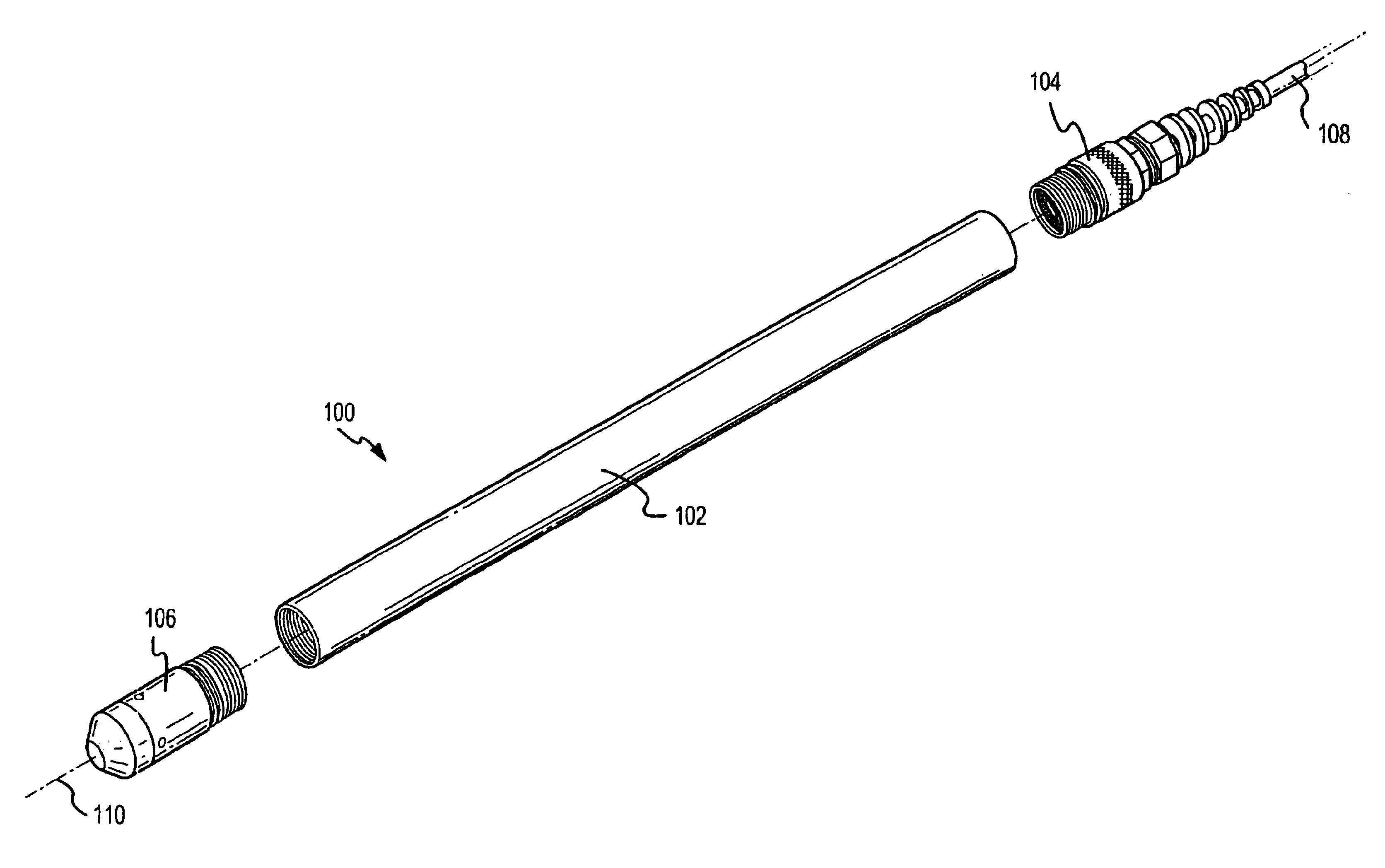
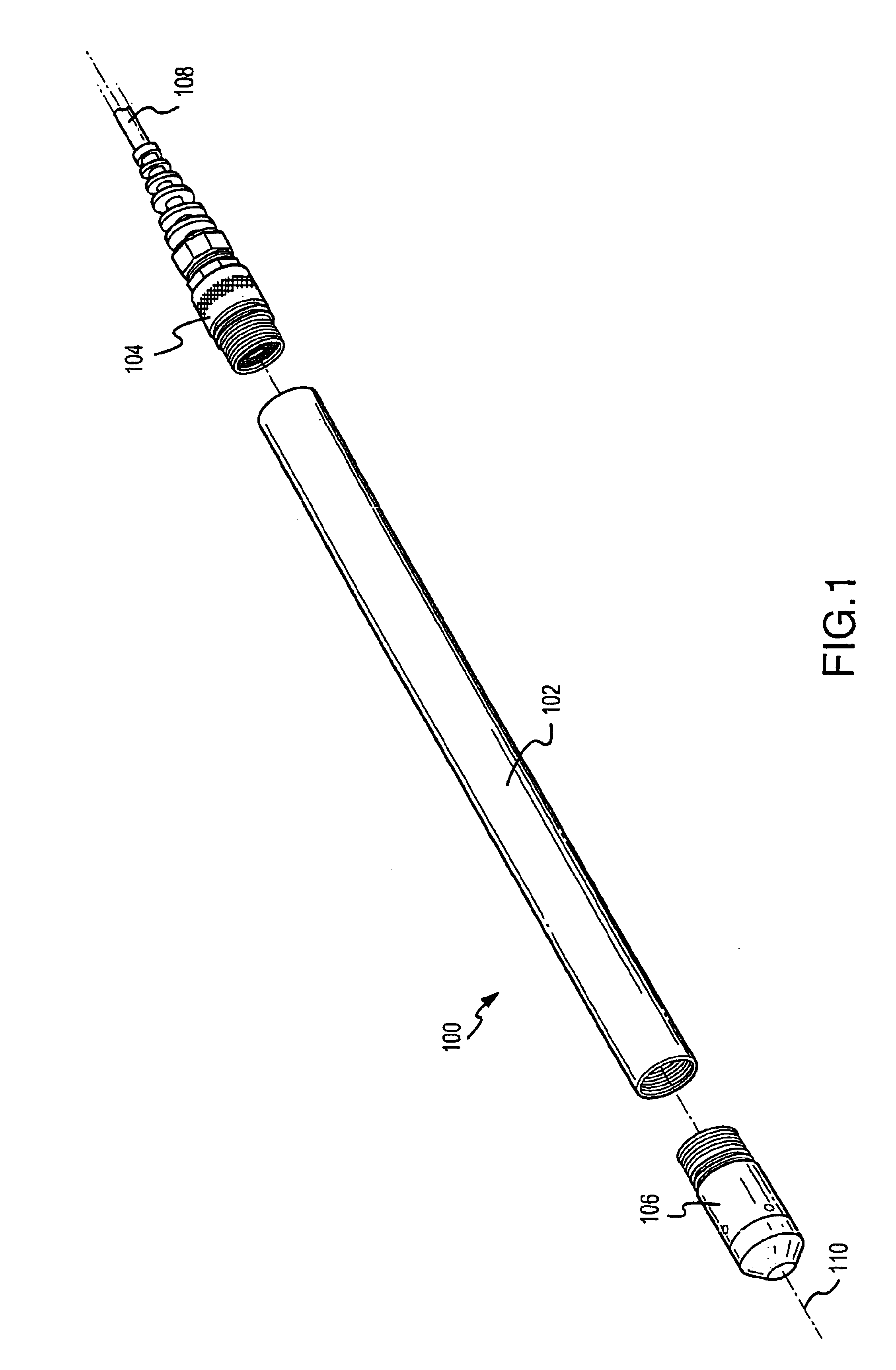
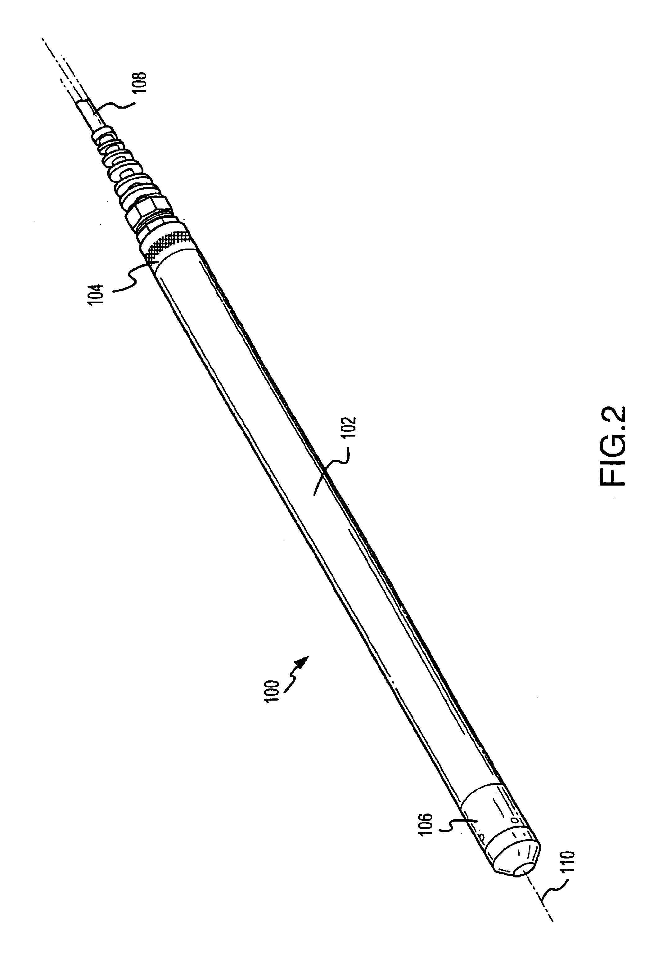
[0063]In one aspect, the present invention provides a tool assembly and components that are assemblable to make the tool assembly. The tool assembly, and each of the components from which the tool assembly is assemblable, are adapted for insertion into a well or other hole for the purpose of monitoring at least one condition present in the well or other hole. At least one component of the tool assembly includes a computing unit capable of directing at least one operation of the tool assembly, and preferably substantially all operations of the tool assembly, the computing unit includes a processor and memory having stored therein instructions readable and executable by the processor to direct operation of the tool assembly. The tool assembly also includes a sensor, which may be located in the same component with the computing unit or may be located in a different component. The sensor is capable of providing sensor readings to the computing unit, with each sensor reading including ge...


PUM


Abstract

The present invention provides a tool assembly for use in field applications to monitor at least one condition in a well or other hole. The tool assembly may include a computing unit for directing operation of the tool assembly and may be sized to be operable in a hole having a diameter of 1 inch, and in some cases even smaller. In one aspect, the tool assembly is designed to significantly conserve power. Sensor readings may be taken at different schedules to conserve power when frequent readings are not required. Also, internal electronics of the tool assembly can be operated at a low voltage. In one aspect, the tool assembly is assemblable by simple rotatable engagement of the components, with electrical interconnections being made automatically by the rotatable engagement without keying of components. In another aspect, the tool assembly is networkable with other like tool assemblies and monitorable from a central location. In yet another embodiment, the tool assembly may include a tool bundle with a plurality of different sensor capabilities useful as a multi-parameter probe when tool diameter is not a big concern.

Description

RELATED APPLICATIONS[0001]This patent application relates to U.S. provisional patent application Ser. No. 60 / 156,913 filed on Sep. 30, 1999.FIELD OF THE INVENTION[0002]The present invention involves a tool assembly and components from which the tool assembly is assemblable, which are typically of an elongated tubular shape adapted for insertion into wells for field monitoring of conditions in the wells; and in particular a rotatably engageable connector to couple and electrically interconnect components, data collection, processing and storage functions, networkability and adaptation for use in very small holes.BACKGROUND OF THE INVENTION[0003]An ever increasing emphasis is being placed on systematic monitoring of environmental conditions in relation to ground and surface water resources. Examples of some situations when monitoring of conditions of a water resource may be desired include environmental monitoring of aquifers at an industrial site to detect possible contamination of t...

Claims


Application Information

Patent Timeline
IPC IPC(8): E21B49/00E21B17/02E21B41/00E21B47/00E21B47/12
CPCE21B17/023E21B17/028E21B41/0085E21B47/00E21B47/122E21B47/13
Inventor HENRY, KENT D.GRAY, ZACHARY A.WATSON, MARK A.SMITH, STANLEY B.KREITMAN, KOREY L.
Owner INSITU INC
Why Eureka
Try Eureka