Optic for industrial endoscope/borescope with narrow field of view and low distortion

Inactive Publication Date: 2005-08-16
LAWRENCE LIVERMORE NAT SECURITY LLC
View PDF18 Cites 12 Cited by
  • Summary
  • Abstract
  • Description
  • Claims
  • Application Information

AI Technical Summary

Benefits of technology

[0010]Another object of the invention is to provide an optic designed to

Problems solved by technology

Current inspection methods depend upon either the visual judgement of a human operator and/or the costly and time consuming disassembly of complex or hazardous hardware.
In industrial or laboratory settings, it can be either not cost effective or too hazardous to perform such work.
Also, the measurement of the surface roughness in the turbine blades of an electrical power generator, for example, can put a unit out of

Method used


Image

  • Optic for industrial endoscope/borescope with narrow field of view and low distortion
  • Optic for industrial endoscope/borescope with narrow field of view and low distortion
  • Optic for industrial endoscope/borescope with narrow field of view and low distortion

Examples


Embodiment Construction

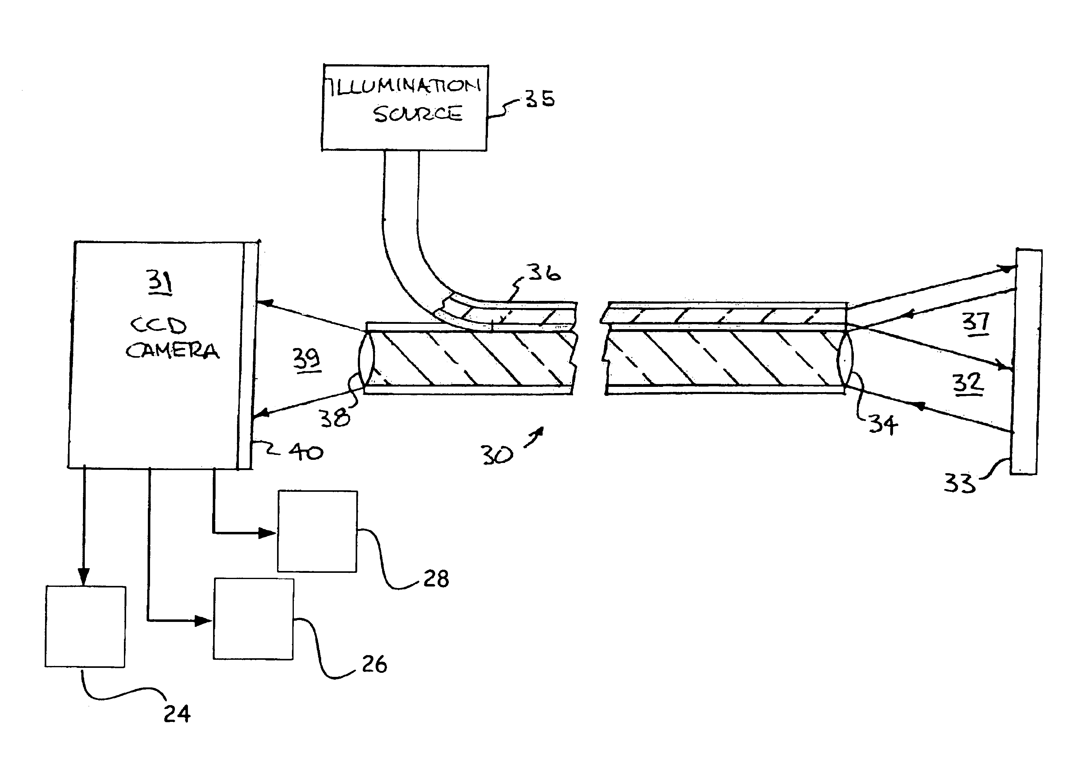
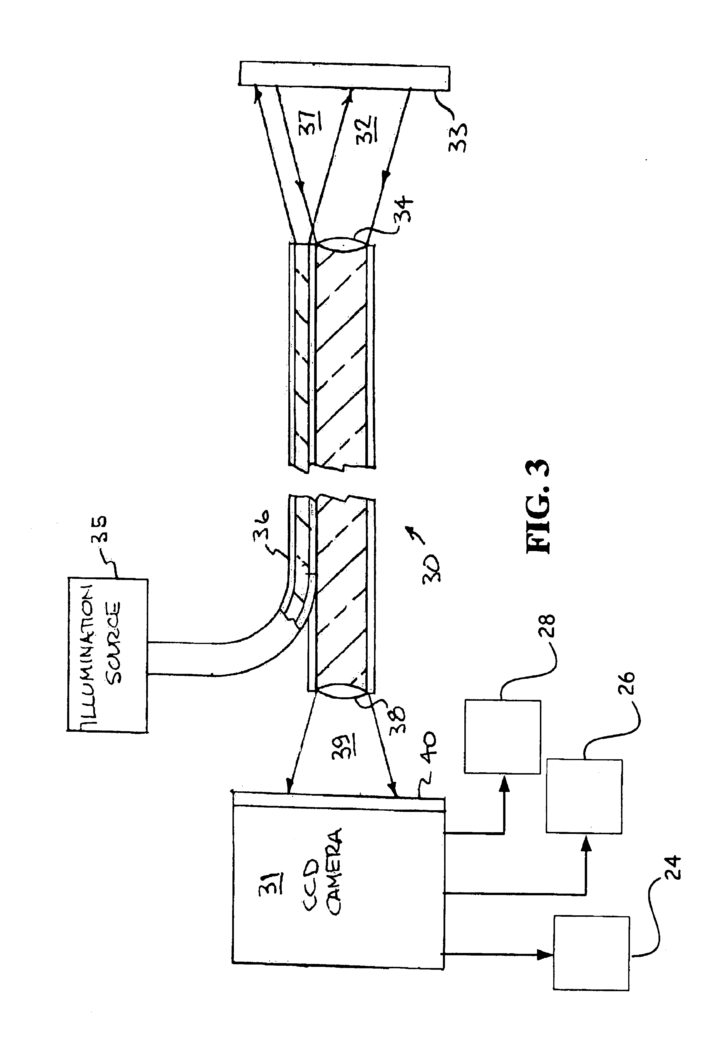
[0020]The present invention is directed to an optic optimized for high spatial resolution, minimal nonlinear magnification distortion (pin cushion / barrel type optical distortion) while at the same time having a prescribed chromatic focal shift. It is this chromatic focal shift that is normally designed out of an optical system that is used to take the data required far non-contact surface roughness measurements. The chromatically shifted images are generated with a broad band visible spectrum illumination system. The images are collected by the optic and relayed either onto a coherent fiber optic image bundle of an endoscope, such as shown in FIG. 3, or onto the image plane of the relay image sets of a rigid borescope. The images are recorded onto the image plane of a color CCD camera, see FIG. 3. The composite video image is digitized and stored electronically with a frame grabber or other image recording device and then split into separate color image channels e.g., red 24, green ...


PUM


Abstract

An optic for the imaging optics on the distal end of a flexible fiberoptic endoscope or rigid borescope inspection tool. The image coverage is over a narrow (<20 degrees) field of view with very low optical distortion (<5% pin cushion or barrel distortion), compared to the typical <20% distortion. The optic will permit non-contact surface roughness measurements using optical techniques. This optic will permit simultaneous collection of selected image plane data, which data can then be subsequently optically processed. The image analysis will yield non-contact surface topology data for inspection where access to the surface does not permit a mechanical styles profilometer verification of surface topology. The optic allows a very broad spectral band or range of optical inspection. It is capable of spectroscopic imaging and fluorescence induced imaging when a scanning illumination source is used. The total viewing angle for this optic is 10 degrees for the full field of view of 10 degrees, compared to 40-70 degrees full angle field of view of the conventional gradient index or GRIN's lens systems.

Description

[0001]The United States Government has rights in this invention pursuant to Contract No. W-7405-ENG-48 between the United States Department of Energy and the University of California for the operation of Lawrence Livermore National Laboratory.BACKGROUND OF THE INVENTION[0002]The present invention relates to imaging optics, particularly to optics on the distal end of a flexible fiberoptic endoscope or rigid borescope inspection tool, and more particularly to an optic having a narrow (<20 degrees) field of view with very low optical distortion (<5% pin cushion or barrel distortion), while at the same time having a prescribed chromatic focal shift.[0003]Current inspection methods depend upon either the visual judgement of a human operator and / or the costly and time consuming disassembly of complex or hazardous hardware. In industrial or laboratory settings, it can be either not cost effective or too hazardous to perform such work. In addition, the operators subjective visual judg...

Claims


Application Information

Patent Timeline
IPC IPC(8): A61B1/00A61B1/04G02B27/00G02B23/24G02B6/42
CPCA61B1/00096A61B1/00165A61B1/0638G02B23/243G02B27/0025G02B6/4298
Inventor STONE, GARY F.TREBES, JAMES E.
Owner LAWRENCE LIVERMORE NAT SECURITY LLC
Why Eureka
Try Eureka