Continuous calibration of a non-contact thermal sensor for laser sintering

a non-contact thermal sensor and laser sintering technology, applied in the field of freeform fabrication, can solve the problems of reducing the accuracy of measurement, slow contact sensor, prone to disturbance or jarring, etc., and achieves high repeatability, accurate monitoring, and consistent mechanical properties.

Active Publication Date: 2005-08-16
3D SYST INC
View PDF14 Cites 161 Cited by
  • Summary
  • Abstract
  • Description
  • Claims
  • Application Information

AI Technical Summary

Benefits of technology

[0019]It is an advantage of the present invention that the build temperatures within the process chamber of the laser sintering system are accurately monitored throughout the build process.
[0020]It is another advantage of the present invention that the laser sintering system is automatically calibrated on a layer-by-layer basis throughout the build to enable parts to be built with highly consistent mechanical properties throughout the part geometry and to be highly repeatable from build-to-build and system-to-system.
[...

Problems solved by technology

The basic problem with attempting to accurately sense the temperature of the powder in a laser sintering system is the fact that contact measurements cannot be made of the powder since powder is constantly in flux during the laser sintering process.
Additionally contact sensors are slow, position sensitive, and prone to being disturbed or jarred by bumping.
Because of this and since there is no way to ensure consistent contact with the powder without interfering with the powder's movement and hence reducing the accuracy of the measurement, IR sensors have been utilized to attempt to accurately determine the temperature of the powder within the process chamber.
However, the use of a single infrared (IR) sensor focused on one spot on the target surface has some known limitations.
These include the lack of a uniform temperature across the entire target surface, possible thermal gradients from front-to-back and from side-to-side of the process chamber and part powder bed, and the fact that the recently fused part in the syste...

Method used


Image

  • Continuous calibration of a non-contact thermal sensor for laser sintering
  • Continuous calibration of a non-contact thermal sensor for laser sintering
  • Continuous calibration of a non-contact thermal sensor for laser sintering

Examples


Embodiment Construction

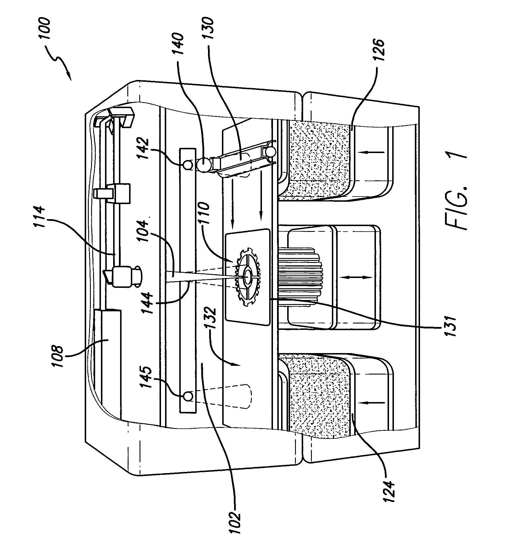
[0028]FIG. 1 illustrates a rendering of a selective laser sintering system indicated generally by the numeral 100. Such a system is currently sold by 3D Systems, Inc. of Valencia, Calif. FIG. 1 is a rendering shown with the doors removed for clarity. A carbon dioxide laser and its associated optics are shown mounted in a unit above a process chamber 102. The process chamber 102 includes a powder bed 132, two powder feed systems 124 and 126, and a leveling roller 130. A black body radiation emitter 140 is shown mounted to the leveling or counter-rotating roller 130. Within the process chamber 102 the appropriate temperature and atmospheric composition for the fabrication of the article are maintained. The atmosphere is typically an inert atmosphere, such as nitrogen.

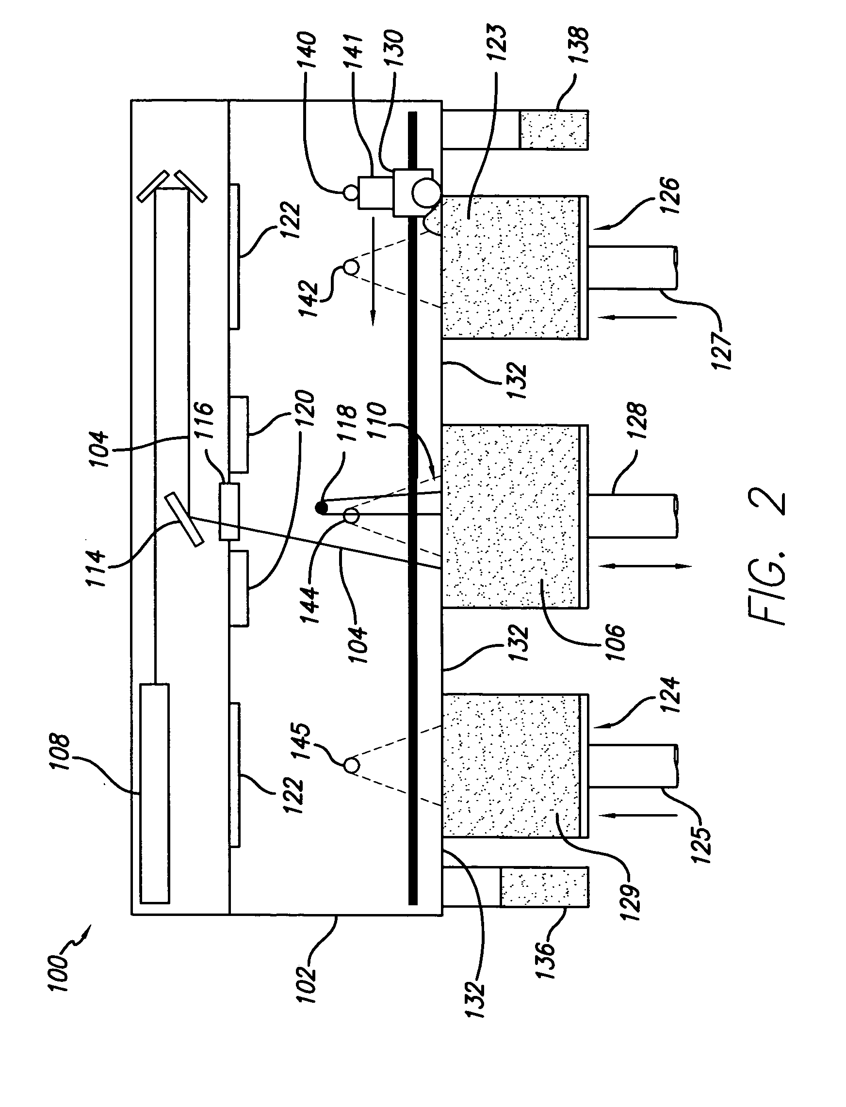
[0029]Operation of this conventional selective laser sintering system 100 is shown in FIG. 2 in a front view of the system with the doors removed for clarity to illustrate the laser sintering process. A laser beam 104 is ...


PUM

PropertyMeasurementUnit
Areaaaaaaaaaaa
Energyaaaaaaaaaa

Abstract

An apparatus and a method of using the apparatus wherein a radiation emitter is positioned adjacent a sensor apparatus within a process chamber in a laser sinter system that emits radiation to the sensor apparatus and a calibration apparatus receives readings from the sensor apparatus to compare temperature sensings received from the sensor apparatus with set emission signals from the radiation emitter to adjust the temperature sensings to calibrate the sensor apparatus during the forming of a three-dimensional article. The calibration is done repeatedly during the build process of the three-dimensional article.

Description

BACKGROUND OF THE INVENTION[0001]This invention relates to the field of freeform fabrication, and more specifically is directed to the fabrication of three-dimensional objects by selective laser sintering utilizing an improved thermal sensing system to ensure accurate temperature sensings of the powder part bed.[0002]The field of freeform fabrication of parts has, in recent years, made significant improvements in providing high strength, high density parts for use in the design and pilot production of many useful articles. Freeform fabrication generally refers to the manufacture of articles directly from computer-aided-design (CAD) databases in an automated fashion, rather than by conventional machining of prototype articles according to engineering drawings. As a result, the time required to produce prototype parts from engineering designs has been reduced from several weeks to a matter of a few hours.[0003]By way of background, an example of a freeform fabrication technology is th...

Claims


Application Information

Patent Timeline
IPC IPC(8): B23K26/00B23K26/34B29C35/08B29C67/00G01J5/52
CPCB23K26/34B29C67/0077B29C67/0088G01J5/522B23K35/0244B23K26/3246B23K26/3273B23K26/3293B23K26/3206B29C2035/0822B29C2037/90B22F3/1055B22F2003/1057B23K26/32B23K26/324B29C64/153B23K2101/34B23K2103/08B23K2103/30B23K2103/50B23K2103/52B33Y30/00B33Y10/00G01J5/004B29C64/393Y02P10/25G01J5/53G01J5/80B22F12/41B22F12/13B22F10/31B22F10/28B22F12/49B22F10/73B22F12/55B22F12/90
Inventor CHUNG, TAE MARKPARTANEN, JOUNI P.
Owner 3D SYST INC
Why Eureka
Try Eureka