Endoscope having red component cut filter

a technology of endoscope and filter, which is applied in the field of endoscope, can solve the problems of inability to obtain contrast between mucosa, blood vessels, other tissues, and inability to distinguish mucosa, so as to improve the redness of an image, keep brightness and sharpness, and good contrast

Inactive Publication Date: 2005-08-23
FUJI PHOTO OPTICAL CO LTD
View PDF9 Cites 7 Cited by
  • Summary
  • Abstract
  • Description
  • Claims
  • Application Information

AI Technical Summary

Benefits of technology

[0013]The present invention has been achieved in view of the above described problem, and has an object to provide an endoscope capable of improv

Problems solved by technology

However, there is a problem that hemoglobin in blood also exists in peripheral tissue, thus entire sites in vivo have redness to cause unclear distinction between the mucosa and the blood vessel, or other tissue.
However, the infrared cut filter is simply for removing the infrared radia

Method used


Image

  • Endoscope having red component cut filter
  • Endoscope having red component cut filter
  • Endoscope having red component cut filter

Examples


first embodiment

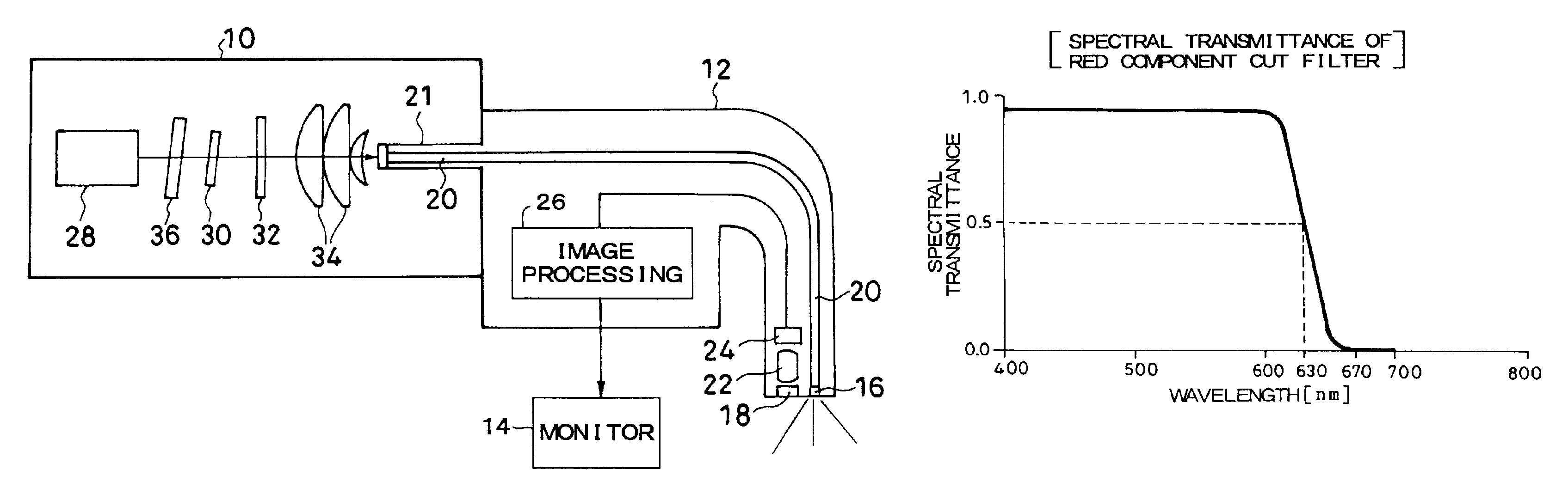
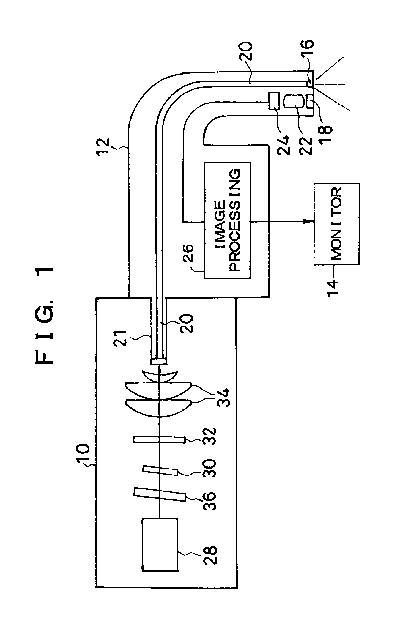
[0032]FIG. 1 shows a configuration of a part of an electronic endoscope according to a first embodiment. The electronic endoscope includes a light source 10, a scope and processor unit 12, and a monitor 14. In FIG. 1, the scope and processor unit 12 has an illumination window 16 and an observation window 18 at a tip of a scope, and a light guide 20 connects to the illumination window 16 and extends to a connector 21 to connect to the light source 10. To the observation window 18, a CCD 24 that is an image pickup device optically connects via an objective optical system 22.

[0033]An electronic endoscope having a zoom mechanism includes a movable lens, as a part of the objective optical system 22, that is moved back and forth such as by an unshown rotating linear transfer member. The linear transfer member is driven by, for example, a motor, and the back and forth movement of the movable lens provides an optically enlarged image.

[0034]After the CCD 24, an image processing circuit 26 is...

second embodiment

[0043]FIG. 6 shows a configuration of a second embodiment in which a red component cut filter is placed in a position different from the position in the first embodiment. As shown in FIG. 6, in the second embodiment, the red component cut filter is not placed immediately after a light source 28, but a red component cut filter member 38 in which a coating for cutting a red component is applied across an optical plate member is provided as a light entrance end member of a light guide 20 in a connector 21 in a scope and processor unit 12.

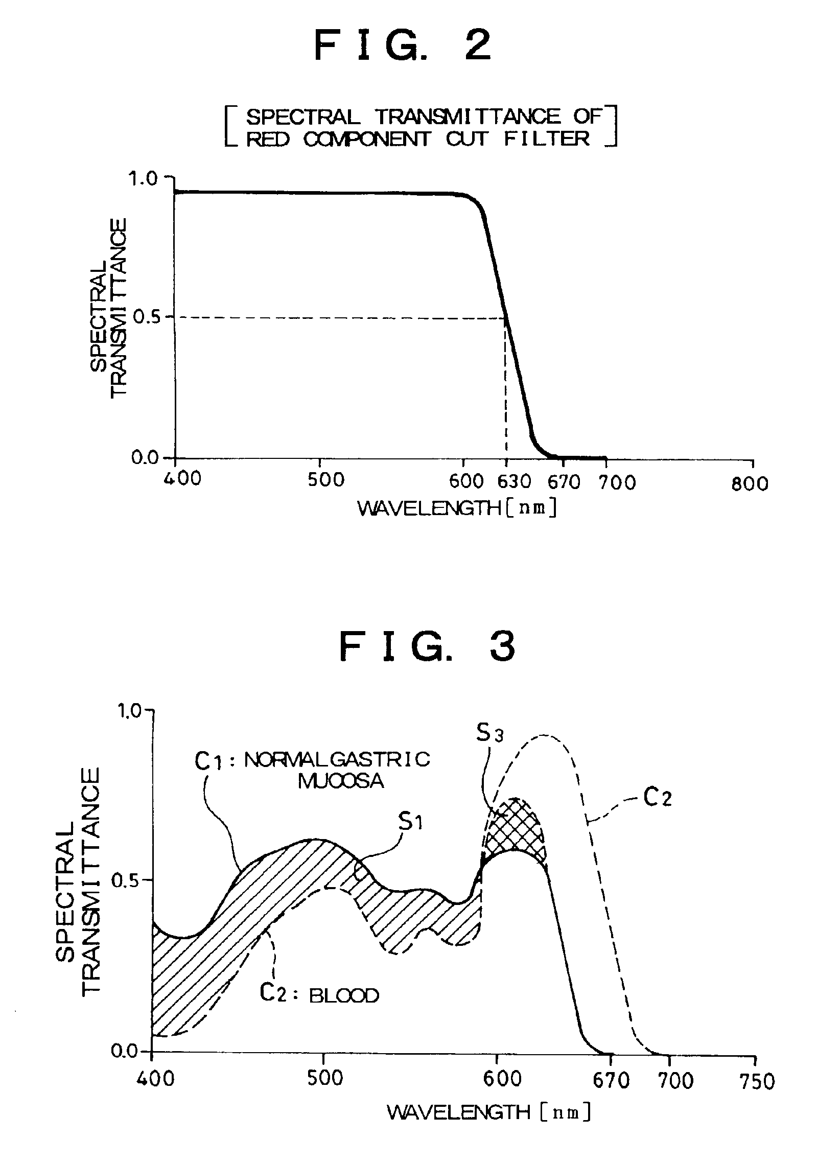
[0044]The red component cut filter member 38 has a filter characteristic like the filter characteristic in FIG. 2, and the second embodiment allows obtaining the advantage explained in FIG. 3. The red component cut filter may be provided at other places, for example, at a midway through the light guide 20, or a light emitting end of the light guide 20 at a tip of a scope.

[0045]As described above, the first and second embodiments restrain the scattering...

third embodiment

[0046]FIG. 7 shows a main configuration of an electronic endoscope according to a third embodiment. The electronic endoscope includes a light source 110, a processor unit 111, a scope 112, and a monitor 14. Like the fist embodiment, the light source 110 connects to a light guide 20 connecting to an illumination window 16 at a tip of the scope 112, and to an observation window 18, a CCD 24 optically connects via an objective optical system 22.

[0047]The CCD 24 is driven and controlled by a CCD drive circuit 126, to which a scope side microcomputer 130 connects via a timing generator (TG) 128. To the microcomputer 130, a ROM 131 connects that stores various data for image processing, and limit value data of gain control when a red component cut filter (154) described later is used.

[0048]A CDS (correlated double sampling) / AGC (auto gain control) circuit 132 is provided on an output side of the CCD 24, and amplifies an image signal to match a control value received from the microcomputer...


PUM


Abstract

An endoscope includes a red component cut optical filter having a characteristic that a spectral transmittance becomes half at 630 nm and zero at 670 nm, for example between a light source and an infrared cut filter, to remove a long wavelength component mainly in a red band of illumination light. This restrains scattering of light on a long wavelength side of red light, and allows taking images of mucosa, blood vessels, and other tissue in good contrast in an object to be observed and satisfactorily observing them on a monitor. Further, reduction in light amount resulting from cutting a red component with the filter is eliminated by light amount control with an aperture and gain control of a signal.

Description

BACKGROUND OF THE INVENTION[0001]This application claims the priority of Japanese Patent Applications No. 2001-288182 filed on Sep. 21, 2001 and No. 2001-295270 filed on Sep. 27, 2001 which are incorporated herein by reference.[0002]1. Field of the Invention[0003]The present invention relates to an endoscope, and more particularly, to supply of illumination light and signal processing in an endoscope that allows observation of fine structure, enlarged by optical zooming, of blood vessels or the like of an object to be observed.[0004]2. Description of the Related Art[0005]An endoscope, for example, an electronic endoscope takes an image, by an image pickup device such as a CCD (Charge Coupled Device), of an object to be observed, captured via an objective optical system by applying illumination light, and displays an image of the object to be observed on a monitor or the like. Recently, a movable lens has been incorporated into the objective optical system, and the movable lens is mo...

Claims


Application Information

Patent Timeline
IPC IPC(8): A61B1/04
CPCA61B1/00096A61B1/0638A61B1/0646A61B2562/0242A61B1/0655
Inventor AYAME, DAISUKEHIGUCHI, MITSURUABE, KAZUNORITAKEUCHI, SHINJI
Owner FUJI PHOTO OPTICAL CO LTD
Why Eureka
Try Eureka