E-field-modulated bistable molecular mechanical device

a mechanical device and field-modulated technology, applied in the field of electronic and optical devices, can solve the problems of slow switching times of molecules, irreversible switches, and large energy expenditure to toggle switches, and achieve the effects of small band gaps, small band gaps, and large band gaps

Inactive Publication Date: 2005-08-23
HEWLETT PACKARD DEV CO LP
View PDF1 Cites 8 Cited by
  • Summary
  • Abstract
  • Description
  • Claims
  • Application Information

AI Technical Summary

Problems solved by technology

The primary problem with the rotaxane was that it is an irreversible switch.
This requires the expenditure of a significant amount of energy to toggle the switch.
In addition, the large and complex nature of rotaxanes and related compounds potentially makes the switching times of the molecules slow.
The primary problems with the catenanes are small ON-to-OFF ratio and a slow switching time.

Method used


Image

  • E-field-modulated bistable molecular mechanical device
  • E-field-modulated bistable molecular mechanical device
  • E-field-modulated bistable molecular mechanical device

Examples


second embodiment

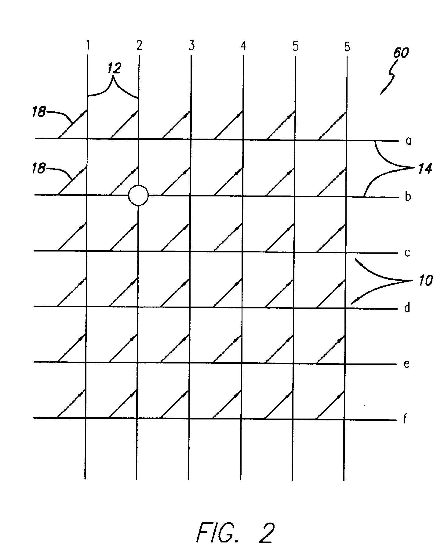
[0069]Since each colorant molecule in colorant layer 301 is transparent outside of the colorant absorption band, then multiple colorant layers may be superimposed and separately addressed to produce higher resolution color displays than currently available. FIG. 4 is a schematic illustration of this A high resolution, full color, matrix addressable, display screen 400 comprises alternating layers of transparent electrodes—row electrodes 401, 403 and column electrodes 402 and 404—and a plurality of colorant layers 405, 407, 409, each having a different color molecule array. Since each pixel in each colorant layer may be colored or transparent, the color of a given pixel may be made from any one or a combination of the color layers (e.g., cyan, magenta, yellow, black) at the full address resolution of the display. When all colorant layers 405, 407, 409 for a pixel are made transparent, then the pixel shows the background substrate 303 (e.g., white). Such a display offers the benefit ...

third embodiment

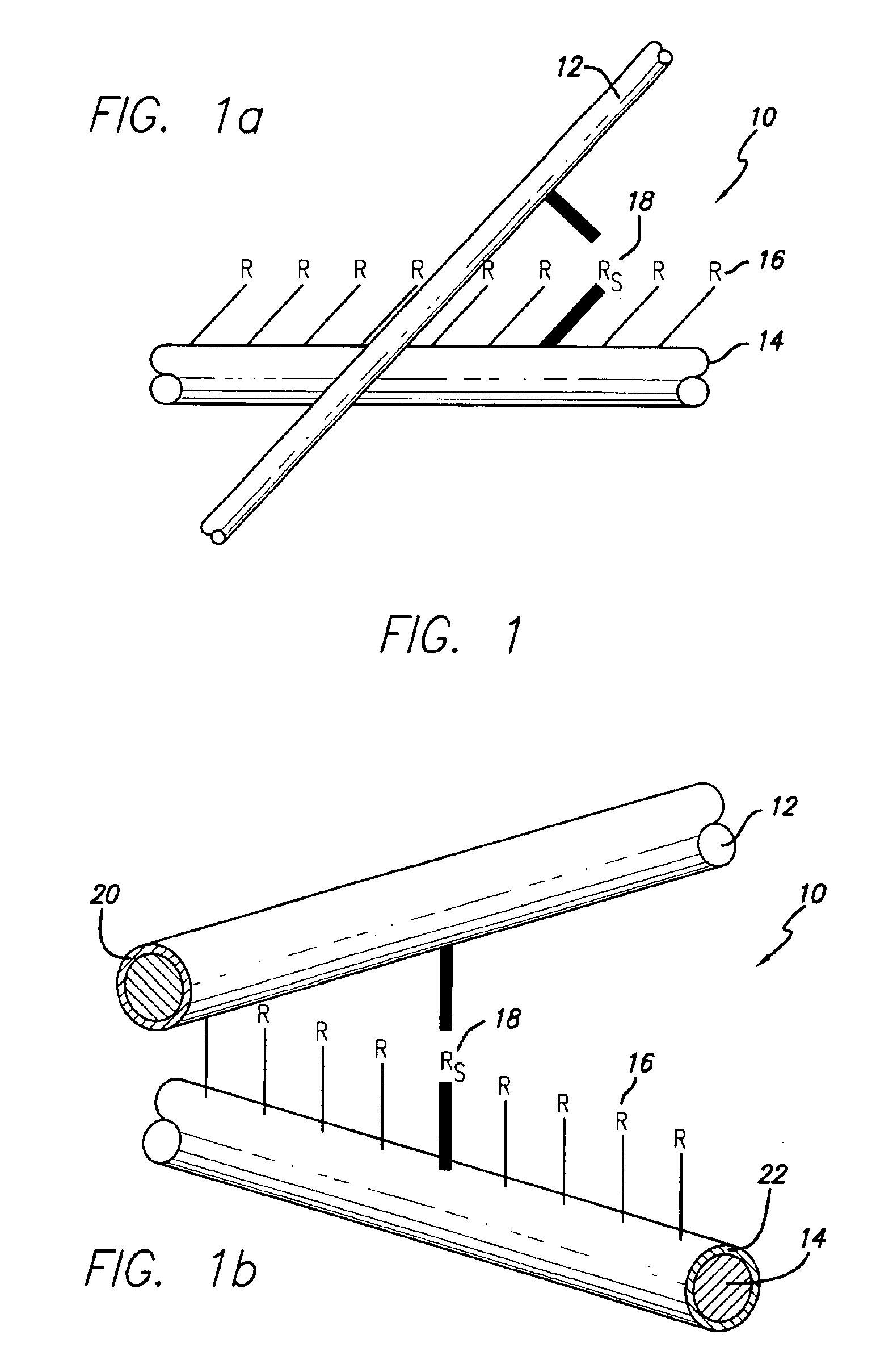
[0072]More specifically, the third embodiment as shown in FIG. 5 comprises a display screen 502, a scanned electrode array 504, and array translation mechanism 501 to accurately move the electrode array across the surface of the screen. The display screen 502 again comprises a background substrate 303, a transparent view-through layer 305, and at least one bi-stable molecule colorant layer 301. The colorant layer 301 may include a homogeneous monochrome colorant (e.g., black) or color mosaic, as described herein above. The scanned electrode array 504 comprises a linear array or equivalent staggered array of electrodes in contact or near contact with the background substrate 303. A staggered array of electrodes may be used, for example, to minimize field crosstalk between otherwise adjacent electrodes and to increase display resolution.

[0073]In operation, each electrode is sized, positioned, and electrically addressed to provide an appropriate electric field, represented by the arrow...

example 1a

[0096 is a generic molecular example of the teachings herein. In this molecule, a Y configuration, similar to that depicted in FIG. 6, is employed. However, in place of the insulating branch 34, a second rotor is employed on the second branch, connected between the junction unit and another stator unit.

where:

[0097]A is an Acceptor group comprising an electron-withdrawing group selected from the group consisting of: (a) hydrogen, (b) carboxylic acid and its derivatives, (c) sulfuric acid and its derivatives, (d) phosphoric acid and its derivatives, (e) nitro, (f) cyano, (g) hetero atoms selected from the group consisting of N, O, S, P, F, Cl, and Br, (h) functional groups with at least one of the hetero atoms, (i) saturated or unsaturated hydrocarbons, and (j) substituted hydrocarbons;

[0098]D is a Donor group comprising an electron-donating group selected from the group consisting of: (a) hydrogen, (b) amines, (c) OH, (d) SH, (e) ethers, (f) saturated or unsaturated hydrocarbons, (g...


PUM

PropertyMeasurementUnit
sizeaaaaaaaaaa
heightsaaaaaaaaaa
diameteraaaaaaaaaa

Abstract

A molecular system is provided for nanometer-scale reversible electronic and optical switches, specifically, electric field-activated molecular switches that have an electric field induced band gap change that occurs via rotation of rotor units connected to immobile stator units. The molecular system has two branches on one side of an immobile junction unit and one or two branches on the opposite side to thereby provide “Y” and “X” configurations, respectively. The ends of the branches opposite the junction unit are connected to, or electrically associated with, other molecular systems or substrates, such as electrodes. The rotor units each rotate between two states as a function of an externally-applied field. Both multi-stable molecular mechanical devices and electric field-activated optical switches are provided.

Description

CROSS-REFERENCE TO RELATED APPLICATIONS[0001]The present application is a continuation-in-part of application Ser. No. 10 / 013,643, filed Nov. 13, 2001 now U.S. Pat. No. 6,751,365, which is a continuation-in-part application of application Ser. No. 09 / 898,799, filed Jul. 3, 2001 now pending, which is a continuation-in-part application of Ser. No. 09 / 844,862, filed Apr. 27, 2001 now U.S. Pat. No. 6,763,158, which in turn is a continuation-in-part application of Ser. No. 09 / 823,195, filed Mar. 29, 2001 now pending, which in turn is a continuation-in-part application of Ser. No. 09 / 759,438, filed Jan. 12, 2001, now U.S. Pat. No. 6,512,119, issued Jan. 28, 2003, which in turn is a continuation-in-part application of Ser. No. 09 / 738,793, filed Dec. 14, 2000, now U.S. Pat. No. 6,663,797, issued Dec. 16, 2003.[0002]The present application is directed to a specific molecular system that involves at least two rotatable segments (rotors) that have a large dipole moment and that each link with ...

Claims


Application Information

Patent Timeline
Patent Type & Authority Patents(United States)
IPC IPC(8): G02F1/01G02B26/02G02F1/15G02F1/17G11C13/02G11C11/56G11C23/00
CPCB82Y10/00G02B26/026G02F1/15G02F1/174G11C11/5664G11C13/0014G11C13/02G11C23/00G11C13/04G11C2213/14G11C2213/71G11C2213/77G11C2213/81
Inventor ZHANG, XIAO-ANZHOU, ZHANG LINWILLIAMS, R. STANLEYVINCENT, KENT D.
Owner HEWLETT PACKARD DEV CO LP
Why Eureka
Try Eureka