
Method and apparatus for free-space optical communication without eletro-optical conversion

a free-space optical and conversion technology, applied in the field of free-space optical communication without eletro-optical conversion, can solve the problems of difficult or impossible signal recognition, electrical wires introduce a practical limit to the physical length or distance over which information can travel, and use wired media for telecommunications and high-speed data communication, etc., to achieve the advantage of less penetrating wavelengths of erdas, the effect of minimizing the disadvantage of less penetrating wavelengths

Inactive Publication Date: 2005-08-23
LIGHTPOINTE COMM
View PDF130 Cites 23 Cited by
  • Summary
  • Abstract
  • Description
  • Claims
  • Application Information

AI Technical Summary

Benefits of technology

[0021]One of the important improvements of the present invention relates to the seamless, all-optical integration of fiber optic links and free-space links in a terrestrial communication network without electro-optical conversion between the free-space and fiber optic links. Another improvement relates to communicating information over fiber optic links and free-space links in a terrestrial optical communication network at wavelengths which do not require frequency conversion. Another improvement relates to operating free-space optical links in a terrestrial optical communication network at laser wavelengths which are safer to human eyesight with sufficient link power margin to avoid many of adverse influences of atmospheric attenuation and divergence. Still another improvement involves operating a terrestrial optical communication network with free-space links at a fundamental wavelength which is compatible with or approximately equal to the fundamental wavelength typically used in long-haul optical communication systems. A further improvement relates to establishing free-space links in a terrestrial optical communication network which are not line-of-sight and without using optical repeaters that require electro-optical conversion. Still a further improvement relates to changing the physical orientation of the optical receivers and transmitters to maximize the link power margins of the optical beam and thereby increase the reliability of the transmission. A last specifically mentioned improvement, among others which are not specifically mentioned here, is to is to implement a relatively low cost, terrestrial, all-optical communication network by making effective use of erbium doped fiber amplifiers (ERDAs).
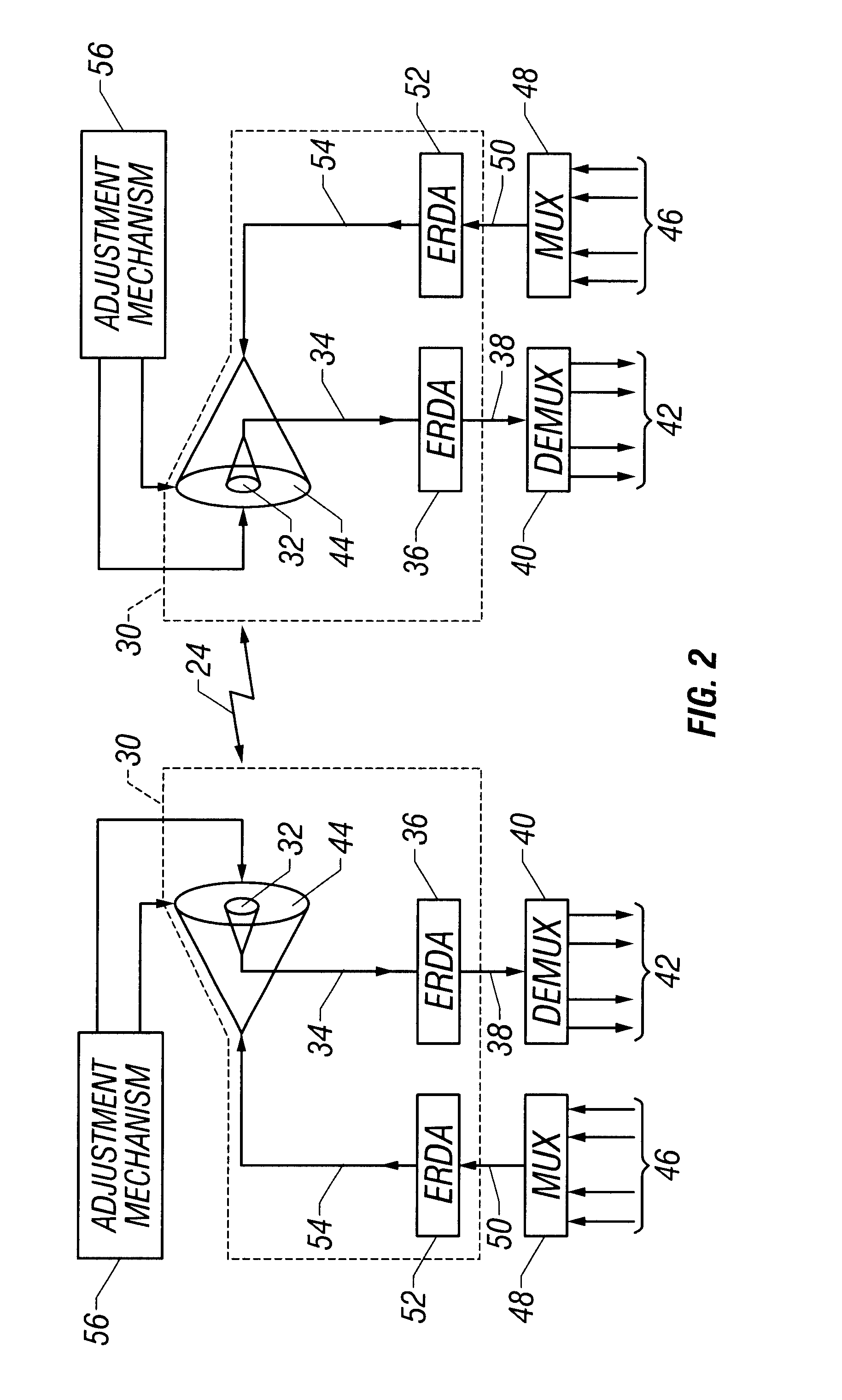
[0022]These and other improvements are attained by a terrestrial optical communication network which comprises a plurality of fiber optic links and free-space links between which optical signals are optically coupled by erbium doped fiber amplifiers (ERDAs), and by a method of terrestrial optical communication which comprises the steps of establishing a plurality of fiber optic links and free-space links between which optical signals are optically coupled without electro-optical conversion, preferably by ERDAs. The ERDAs optically couple the optical signals between the fiber optic and free-space links, thereby avoiding the necessity for electro-optical conversion as the optical signals transition between the free-space and fiber optic links. The relatively inexpensive ERDAs produce all-optical, relatively broad-band amplification, which avoids the necessity for electro-optical conversion. The fundamental wavelength of the ERDAs is also compatible with the fundamental wavelength used in long-haul and backbone communication systems, thereby allowing a convenient integration of the network of the present invention with those communication systems. The fundamental wavelength of the ERDAs is also safer to human eyesight.
[0025]By controlling the power transmitted and received in accordance with these improvements, the disadvantage of the less penetrating wavelengths of the ERDAs is minimized by the higher power available for optical communication. Furthermore, the power control improvements obtain a better quality optical signal for communicating information.

Problems solved by technology

Using wired media for telecommunications and high speed data communications creates difficulties, and these difficulties arise because of the wires.
Electrical wires introduce a practical limit to the physical length or distance over which the information can travel.
Lengthy conductors attenuate the signals to the point where the recognition of signals becomes difficult or impossible.
Furthermore, noise is relatively easily picked up or induced into the wires, and the noise tends to corrupt the signals carried by the wires.
Wire conductor media is also difficult or impossible to install in many situations.
Some metropolitan areas simply have no available space to accommodate the additional conductors within utility conduits, and gaining access to buildings and right-of-way to install the conductors is usually difficult or impossible and is certainly costly.
However, because the atmosphere is freely available for use by all authorized users, the possibility of interference is always present.
Various techniques have been devised to minimize RF interference, but those techniques are relatively expensive to implement.
Furthermore, even those techniques are not effective to assure that enormous amounts of information can be communicated reliably through RF broadcasts, simply because the information is broadcast and can not be confined to secure communication channels or links which could eliminate sources of interference.
Although the disadvantage of fiber optic conductors is that they must be physically installed, the fact that an enormous amount of information can be transmitted over the fiber optic conductors reduces the number of fiber optic conductors which must be installed.
Despite their advantages, optical free-space links present problems.
Furthermore, optical beams naturally diverge as they travel greater distances.
The resulting beam divergence reduces the amount of power available for detection.
If the attenuation of the optical beam is sufficiently great, the ability to recognize the information communicated on a reliable basis is diminished, and the possibility that errors in communication will arise is elevated.
Unfortunately, the more penetrating frequencies are sometimes also the ones which can easily damage human eyes.
To maintain safety while still avoiding some of the problems from atmospheric attenuation, the amount of power which is optically transmitted at these more penetrating frequencies is substantially limited.
Since the more penetrating frequencies are also subject to beam divergence, reducing the power still complicates the reliable communication of information.
Consequently, the reduced power transmission levels counter-balance the benefits of the lesser atmospheric attenuation at the more penetrating frequencies.
Because of the reduced power at the more penetrating frequencies, the effective length of the free-space optical links is still limited.
Furthermore, the more-penetrating, free-space optical frequencies are different from those frequencies which are typically employed to transmit information over long-haul fiber communication systems.
Additional equipment is required to accomplish the conversion, resulting in an increase in the cost and complexity of the terrestrial optical communications network.
In addition, electro-optical conversions also introduce the possibility that errors will be created during the conversion, particularly under the common situation of the fiber optic signal carrying information at multiple different wavelengths.
Common optical detectors respond to information in a broad frequency range or wavelength band, and this broad-band response destroys the information carried at specific wavelengths.
The complexity of this process raises the possibilities of introducing errors in the information communicated and increases the costs of the equipment used in the terrestrial optical communication network.

Method used


Image

  • Method and apparatus for free-space optical communication without eletro-optical conversion
  • Method and apparatus for free-space optical communication without eletro-optical conversion
  • Method and apparatus for free-space optical communication without eletro-optical conversion

Examples


Embodiment Construction

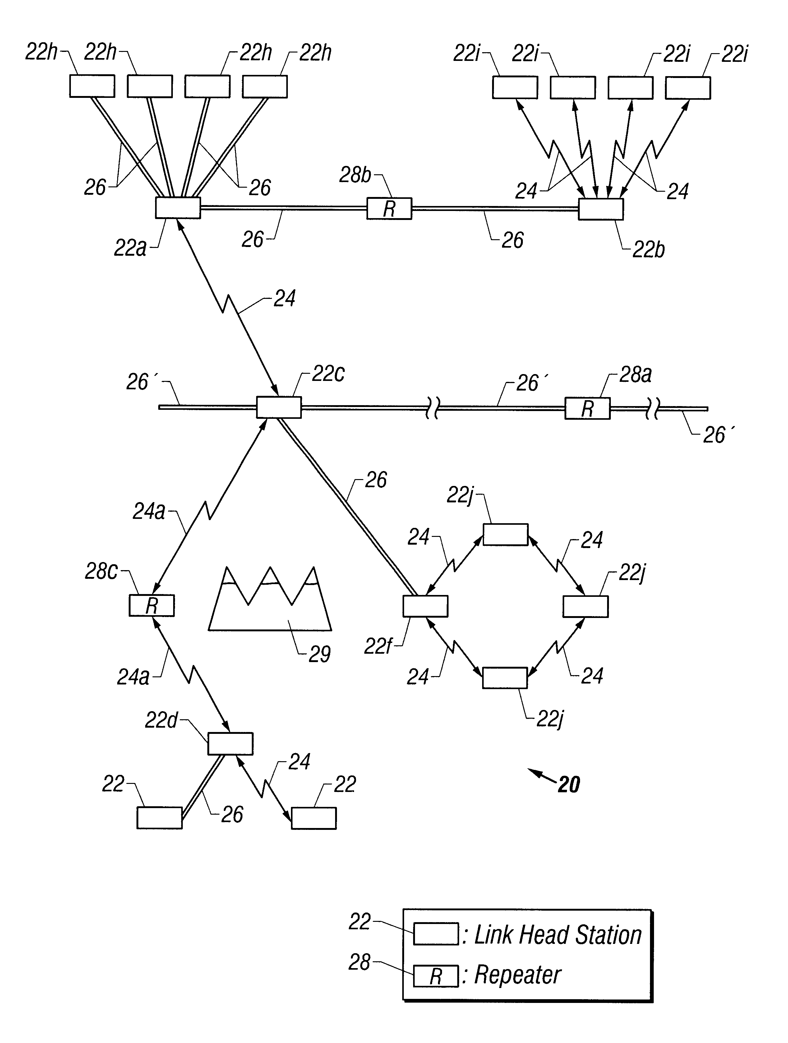
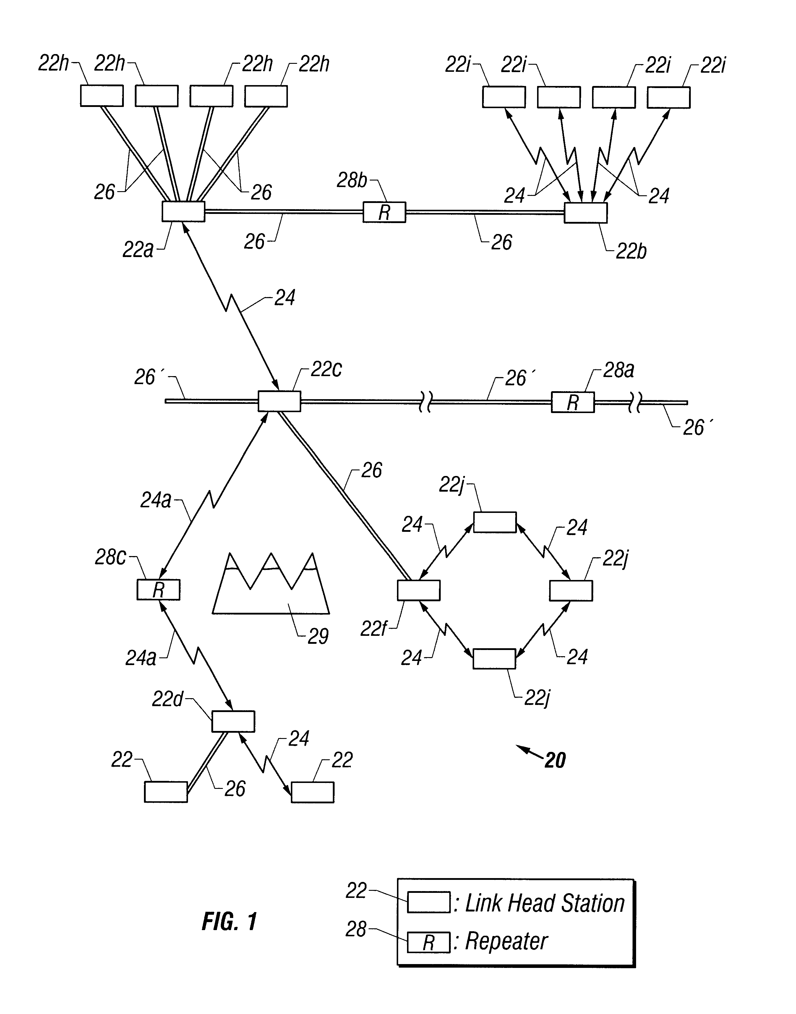
[0042]The improvements of the present invention are incorporated in a terrestrial optical communications network 20 such as is shown in FIG. 1. The terrestrial optical network 20 includes a plurality of link head stations 22 between and through which optical signals are communicated. The optical signals are conducted over free-space optical links 24 and fiber optic conductor links 26 which extend between the link head stations 22. The free-space links 24 and the fiber links 26 are integrated together in the network 20 in a seamless manner, to avoid electro-optical conversion of the optical signals transferred between the free-space links 24 and the fiber links 26, and to communicate optical signals of the same frequency and wavelength over both the free-space and fiber links, in accordance with the present invention.

[0043]The optical signals conducted over the free-space links 24 and the fiber links 26 are preferably laser beams whose fundamental frequency or wavelength is encoded b...


PUM


Abstract

Erbium doped fiber amplifiers (ERDAs) optically couple optical signals between free-space and fiber optic links of a terrestrial optical communication network. The optical gain of transmitting and receiving ERDAs is controlled to achieve good optical signal communication. Control occurs in response to signals received at the transmitting and receiving ends of the links. Control, status and management information may be communicated optically between link head stations. The physical position of transceivers at opposite ends of the link optical signal paths is also controlled.

Description

CROSS-REFERENCE TO RELATED APPLICATIONS[0001]This patent application is a continuation of prior U.S. patent application Ser. No. 09 / 823,175, filed Mar. 29, 2001 is now 6,462,847, which is a continuation of prior U.S. patent application Ser. No. 09 / 065,685, filed Apr. 24, 1998, now U.S. Pat. No. 6,239,888 B1, which are both hereby fully incorporated herein by reference in their entirety.INTRODUCTION[0002]This invention relates to terrestrial optical communication, and more particularly to a new and improved all-optical terrestrial optical communication network which integrates both fiber and free-space links without requiring electro-optical conversion between the fiber and free-space links, and which achieves a relatively good link power margin for reliable communication in adverse atmospheric conditions, which seamlessly integrates with long-haul fiber backbone links, which provides safety against unintended eye injuries, and which is implemented with relative convenience and cost-...

Claims


Application Information

Patent Timeline
IPC IPC(8): H04J14/02H04B10/10H04Q11/00H04B10/17
CPCH04B10/1125H04B10/2912H04J14/02H04Q11/0062H04Q2011/0026
Inventor WILLEBRAND, HEINZ
Owner LIGHTPOINTE COMM
Learn More