Thermal insulating coating for spacecrafts

a technology of thermal insulation coating and spacecraft, applied in the field of thermal insulation coating for spacecraft, can solve the problems of inability to optimize tps from every point of view, most electronic equipment is susceptible to permanent damage, and tps is subject to other constraints

Inactive Publication Date: 2005-09-06
NASA
View PDF14 Cites 41 Cited by
  • Summary
  • Abstract
  • Description
  • Claims
  • Application Information

AI Technical Summary

Benefits of technology

[0008]One means for storing thermal energy involves the utilization of the latent heat of phase change materials. Usually the heat of melting is utilized. The heat required to melt a substance is 80 to 100 times larger than the heat required to raise its temperature one degree. The energy density of heat storage becomes in the order of 0,1 MWh / m3. The use of liquid-vapor phase change further increases the energy density. The thermal protection system of this invention utilizes this innovative concept to minimize the temperature gain in a substrate. Provided herein is a coating composition for the substrate which includes a phase change material. Phase change materials (PCMs) are latent thermal storage materials. They use chemical bonds to store and release heat. The thermal energy transfer occurs when a material changes from a solid to a liquid, or from a liquid to a solid. This is called a change in state, or “phase.” Solid-solid PCMs are also known. They absorb and release heat (latent heat) in the same manner as solid-liquid PCMs, but they do not change into a liquid state under normal conditions. They merely soften or harden.
[0009]This invention involves the use of solid-liquid PCMs. Initially, these solid-liquid PCMs perform like conventional heat storage materials. Their temperatures rise as they absorb heat energy. Unlike conventional heat storage materials, when PCMs reach the temperature at which they change phase (their melting points) they absorb large amounts of heat without getting hotter. By this invention, then, a coating composition is provided for application to substrates subjected to temperatures above 100° F. The composition includes a resinous binder having a quantity of microspheres incorporated in that binder. A sufficient quantity of microspheres is suspended in the binder to form at least a forty percent solids coating composition by weight. Preferably the binder composition will be loaded with 50 to 60 weight percent of the phase change material. Even higher loadings can be used where the binding properties of the particular resin permit it. The microspheres are microscopic particles in the form of a solid phase change material encapsulated in an inert shell such as a ceramic or polymeric shell. The encapsulated phase change material is one having a melting point in the range of the temperatures to which the substrate is subjected. It can function as a heat absorber during its phase change to protect the substrate.

Problems solved by technology

However, this is not generally the case in today's economy where costs require that vehicles and accessories be reused, even though most electronic equipment is susceptible to permanent damage when exposed to high temperatures.
In fact, in order to meet mission objectives a TPS is subject to other constraints in addition to heat requirements.
As a whole, then, the TPS cannot be optimized from every point of view.
Without effective temperature thwarting, rockets of the future may never offer routine low-cost access to space.
However, they cannot be reused, and they tend to have high drag coefficients.
More important, when the ash deteriorates or wears away and comes off, it tends to erode other areas of the space vehicle, even adversely affecting the tiles.
Further, when a vehicle exceeds hypersonic speeds in the atmosphere, the surrounding air ionizes and creates a plasma sheath that tends to block telemetry and communication.
There are not that many areas where materials technology is so visibly enabling.
As evidence of the fact that metals, ceramics and ablative materials are not entirely satisfactory, an estimated forty thousand hours of maintenance is spent between shuttle flights on refurbishing and replacing components.

Method used


Image

  • Thermal insulating coating for spacecrafts
  • Thermal insulating coating for spacecrafts

Examples


specific embodiments

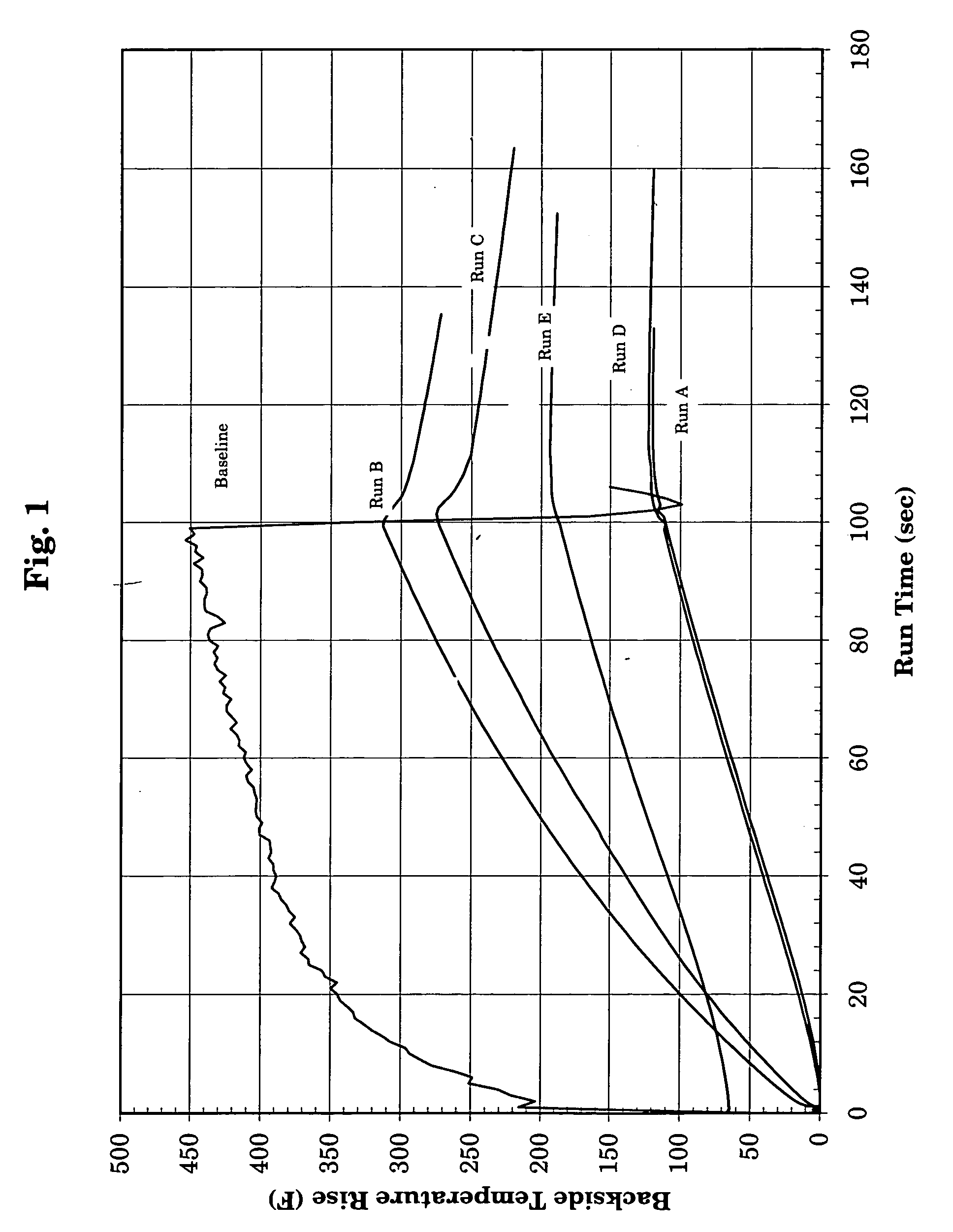
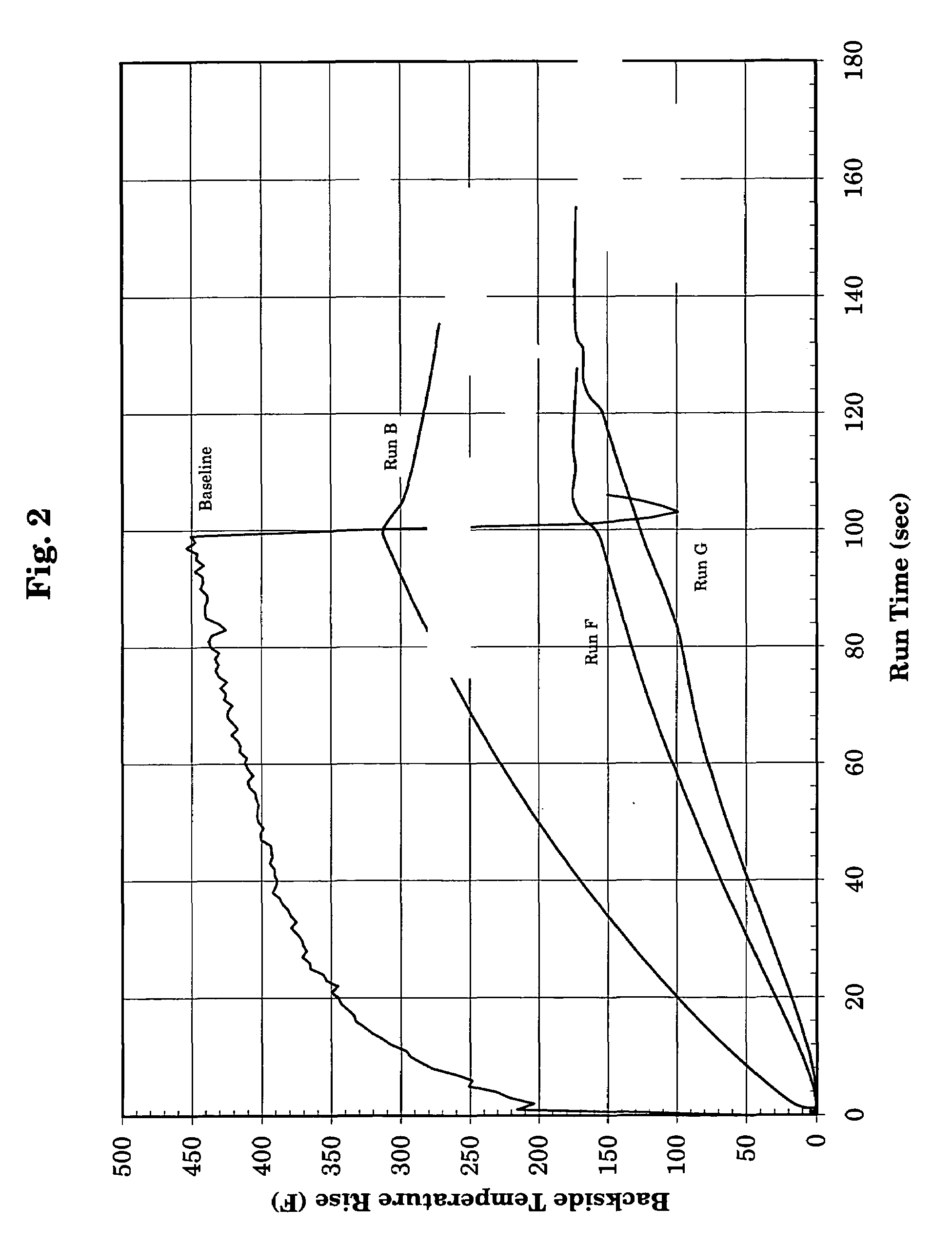
[0019]To further illustrate the invention specific examples will now be given. In these examples, all parts and percentages are by weight unless otherwise specified. In addition, it is frequently desirable to include in the coating composition additional additives, for instance, a UV protecting agent, a fire retardant, or a corrosion inhibitor. In some of the examples this has been done. In addition, in some cases ethanol has been included for achieving a more workable composition. Since it quickly evaporates during the curing of the film, it was not included in the phase change material percent solids calculations. In the examples the number following Thermasorb is its peak transition temperature. It should also be emphasized that although the curing agent is included in the examples which follow, it will be incorporated in the mix prior to the application of the coating compositions as is normal in the case of thermosetting resins.

example 1

[0020]In a suitable reaction vessel equipped with a mechanical stirrer, 72 parts of an epoxide resin made from bisphenol-A and epichlorohydrin and having a molecular weight of less than 400 and an epoxy equivalent in the range of 175 to 200, were mixed with 19 parts of an amine curing agent sold under the trademark Ancamine 1768. To the mix 1 part of a UV protecting agent and 9 parts of the fire retardant, diethyl-N,N-bis(2-hydroxyethyl) amino methyl phosphate were added to form 100 parts of a resinous binder, Coating Composition C.

example 2

[0021]To form a coating composition of this invention, 46 parts of ethyl alcohol were stirred into Coating Composition C. Then 138 parts of a paraffinic hydrocarbon phase change material having a peak transition temperature of 122° F., available as Thermasorb 122, were added to form approximately a 58 percent solids coating composition excluding the alcohol which evaporates, Coating Composition A.


PUM

PropertyMeasurementUnit
temperaturesaaaaaaaaaa
energy densityaaaaaaaaaa
temperaturesaaaaaaaaaa

Abstract

To protect spacecraft and their contents from excessive heat thermal protection systems are essential. For such thermal protection, metal coatings, ceramic materials, ablative materials, and various matrix materials have all been tried, but none have been found entirely satisfactory. The basis for this thermal protection system is the fact that the heat required to melt a substance is 80 to 100 times larger than the heat required to raise its temperature one degree. This led to the use herein of solid-liquid phase change materials. Unlike conventional heat storage materials, when phase change materials reach the temperature at which they change phase they absorb large amounts of heat without getting hotter. By this invention, then, a coating composition is provided for application to substrates subjected to temperatures above 100° F. The coating composition includes a phase change material.

Description

ORIGIN OF THE INVENTION[0001]The invention described in this patent was made by an employee of the United States Government and may be manufactured and used by or for the Government for governmental purposes without the payment of any royalties.CROSS-REFERENCE TO A RELATED APPLICATIONS[0002]There are no applications related to this application.BACKGROUND OF THE INVENTION[0003]Thermal protection systems (TPS) for space vehicles are seldom in the public eye. The general public typically hears only about heat shields and shuttle tiles, and then merely during a manned spacecraft mission. The fact is, thermal protection systems are essential for the successful launch and operation of all spacecraft, whether manned or unmanned.[0004]The obvious goal of a thermal protection system is to keep excessive heat from destroying or damaging a vehicle or its contents. Thermal protection is not as important in vehicles that are designed to be expendable, or to function only for a short time. Howeve...

Claims


Application Information

Patent Timeline
Patent Type & Authority Patents(United States)
IPC IPC(8): B32B5/16B64G1/22B64G1/58C09D5/18C09D7/61C09K5/06
CPCB64G1/226B64G1/58C09D5/18C09K5/063C09D7/1291C08K9/10Y10T428/2998Y10T428/254Y10T428/25Y10T428/2991C09D7/70C09D7/61
Inventor KAUL, RAJ K.
Owner NASA
Why Eureka
Try Eureka