Eureka AIR delivers breakthrough ideas for toughest innovation challenges, trusted by R&D personnel around the world.

Lithium secondary cell

a secondary cell and lithium technology, applied in secondary cell servicing/maintenance, cell components, jackets/cases materials, etc., can solve the problems of high cell temperature, high cell temperature, and high cell temperature, so as to reduce the specific surface area, the effect of high reactivity

Inactive Publication Date: 2005-09-06
MITSUBISHI CHEM CORP
View PDF12 Cites 25 Cited by
  • Summary
  • Abstract
  • Description
  • Claims
  • Application Information

AI Technical Summary

Benefits of technology

[0017]As a result of an extensive study to accomplish the above object, the present inventors have found that on the basis that a lithium-nickel compound oxide having a specific surface area, is used, the safety at the time of overcharging can be improved by adjusting the value of the surface area per capacity of the lithium secondary cell, and thus have completed the present invention.
[0025]As described above, the lithium-nickel compound oxide is present in a particle state in the positive electrode. Such a particulate lithium-nickel compound oxide (in the present invention, the particulate lithium-nickel compound oxide may sometimes be referred to simply as a lithium-nickel compound oxide) has a high reactivity at such a particle surface, whereby it has been regarded to have a problem in the safety at the time of overcharging. Accordingly, it has been considered better to control the reactivity at the time of overcharging by minimizing the specific surface area of the lithium-nickel compound oxide, in order to improve the safety at the time of overcharging. On the other hand, if the specific surface area of the lithium-nickel compound oxide is reduced, cell characteristics such as charged-discharge characteristics (rate characteristics) at a high current value tend to be deteriorated. And, this problem attributable to the specific surface area has been one of the factors which hinder a practical application of a lithium secondary cell using a lithium-nickel compound oxide.
[0026]In the present invention, from a viewpoint totally different from the prior art concept intended to reduce the reactivity at the time of overcharging by minimizing the specific surface area of the lithium-nickel compound oxide, the high surface reactivity of the lithium-nickel compound oxide is rather utilized to secure the safety of the lithium secondary cell itself at the time of overcharging.
[0028]However, a reaction heat will be generated along with the deactivation at the surface of the lithium-nickel compound oxide. Therefore, if the speed of generation of this reaction heat tends to be too high, the rise of the cell temperature due to the reaction heat tends to be large, whereby a runaway reaction is likely to be induced at the time of overcharging. In the present invention, even in a case where the above reaction heat becomes large, the surface area of the entire lithium secondary cell to the capacity of the lithium secondary cell is adjusted to be relatively large, whereby heat release of the reaction heat will be accelerated, and the runaway reaction of the cell can be suppressed.
[0029]Namely, in the present invention, a lithium-nickel compound oxide having a specific surface area, is employed, and the lithium-nickel compound oxide is positively deactivated at the time of overcharging to quickly bring the lithium secondary cell to a safe state, and the proportion of the surface area to the capacity of the lithium secondary cell is regulated to efficiently release the reaction heat generated by the deactivation and thereby to certainly secure the safety of the lithium secondary cell at the time of overcharging.

Problems solved by technology

Consequently, it is likely that a positive electrode active material or a negative electrode active material, as a material constituting the lithium secondary cell, tends to be chemically unstable, or that internal short circuiting between electrodes takes place, which causes an excessive increase of the cell temperature and so on.
By such generation of a gas, not only bursting, leakage, etc. of the cell is likely to occur, but also, if such a state continues, finally, the cell temperature may increase excessively, whereby the cell is likely to catch fire or explode.
Here, among the above-mentioned methods ① to ④ to secure safety of the cell at the time of overcharging, the method for controlling by means of a safety circuit or the method for mechanically shutting off the charging current by a safety valve, has a problem such that it is required to mount an electronic circuit or a safety valve on the cell, whereby the cost for the cell tends to increase, or there may be a restriction in the design of the cell.
Further, by the above-mentioned method ③ for shutting off the charging current by melting the separator, there may be a case where the runaway reaction at the time of overcharging is so abrupt that melting of the separator may not be made in time, and no adequate safety can be secured at the time of overcharging.
Further, in a case where a gel electrolyte as a non-fluid electrolyte is used as the electrolyte for a lithium secondary cell from the viewpoint of the liquid-holding property, it is likely that the gel electrolyte impregnated into pores of the separator tends to hinder closing of pores by melting of the separator, whereby shutting off of the charging current tends to be incomplete.
Further, in the above-mentioned method ④ for controlling the runaway reaction in the cell at the time of overcharging, by adding to the electrolytic solution an overcharging preventive agent such as an organic additive, an overcharging preventive agent which is not directly involved in the usual charging or discharging of the cell, is added to the electrolytic solution, whereby there may be a case where an adverse effect may be presented to the cell performance other than the overcharging characteristics.
Further, a gas is likely to be generated as a result of the oxidation reaction of the overcharging preventive agent at the time of overcharging, whereby corrosion of instruments by such a generated gas, or leakage, etc. of a toxic gas such as an organic gas may be feared.
As mentioned above, a sufficiently satisfactory technique as a safety measure at the time of overcharging has not yet been presented.

Method used


Image

  • Lithium secondary cell
  • Lithium secondary cell
  • Lithium secondary cell

Examples


example 1

Production of a Positive Electrode

[0185]90 Parts of a lithium-nickel compound oxide having a part of nickel sites substituted by cobalt and aluminum (LiαNiXCoYAlZO2 (α=1.02, X=0.82, Y=0.15, Z=0.03)) (specific surface area: 0.4 m2 / g, average secondary particle size: 10 μm), 5 parts of acetylene black, 5 parts of polyvinylidene fluoride and 80 parts of N-methyl-2-pyrrolidone were kneaded by a kneading machine for 2 hours to form positive electrode coating material 1.

[0186]Then, the positive electrode coating material 1 was coated on an aluminum current collector substrate having a thickness of 20 μm by an extrusion type die coating and dried to form a positive electrode active material layer made of a porous film having an active material fixed on a current collector by a binder, followed by compaction by means of a roll press (calender). Thereafter, the electrode portion was cut into a size of 3 cm×5 cm to obtain positive electrode 1. The thickness of the formed positive electrode ac...

example 2

[0195]Flat plate-shaped cell B was prepared in the same manner as in Example 1 except that two such unit cell elements as prepared in Example 1 were stacked, and their terminals were put together and connected to leads.

[0196]The cell capacity C of the flat plate-shaped cell B was 64 mAh; the cell surface area S was 52.4 cm2; the bonded portion area ratio was 26%; the thickness of the cell was 0.52 mm; and the surface area capacity ratio S / C was 0.82.

[0197]This flat plate-shaped cell B was subjected to an overcharging test.

[0198]In the overcharging test, the upper limit voltage was set to be 10 V, and the cell was charged for 120 minutes from the discharged state at a constant current of 3 C (192 mA). As a result, neither smoking nor ignition of the cell was observed under the overcharged condition, and this flat plate-shaped cell B was confirmed to be a cell which is highly safe and durable against overcharging at 3 C.

example 3

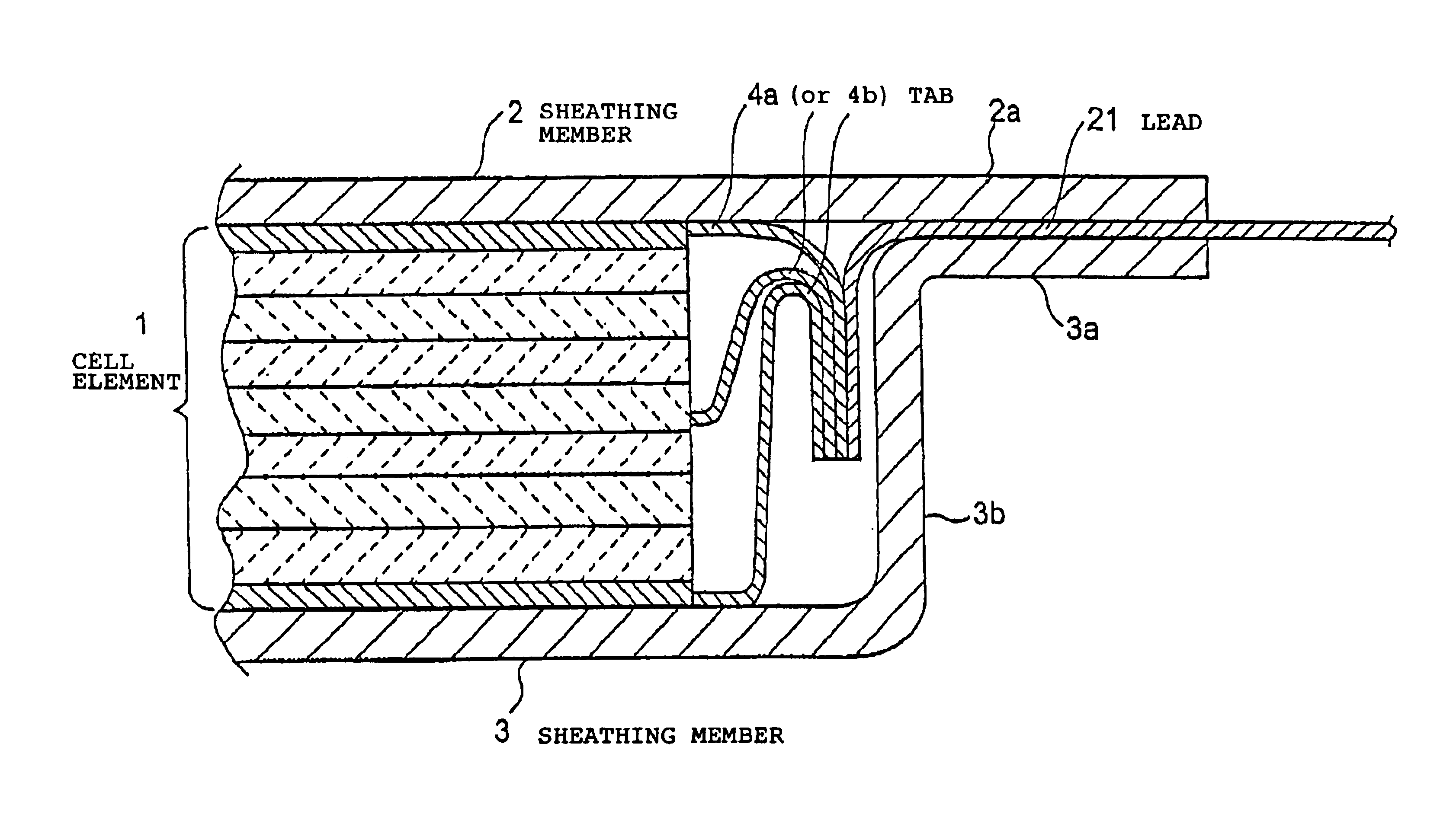
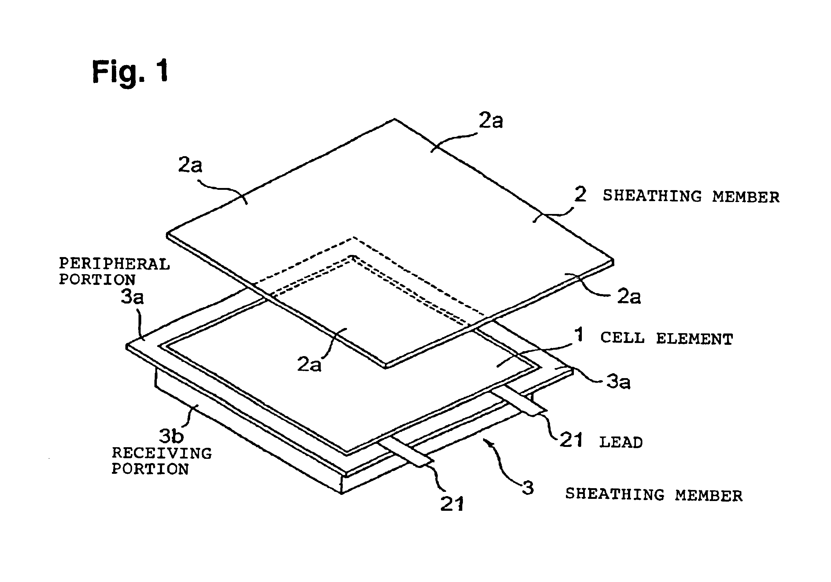
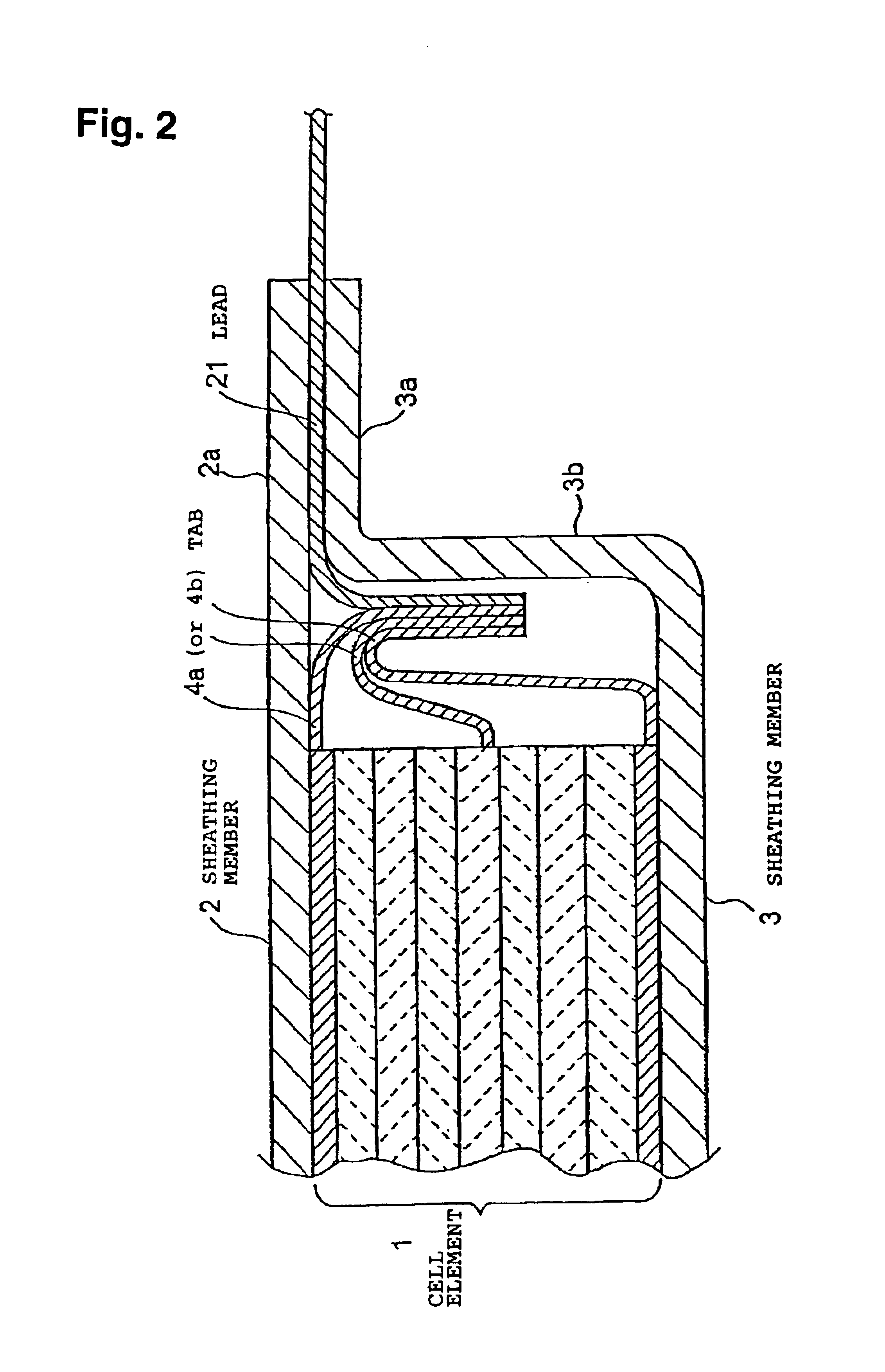
[0199]In Example 1, the size of the positive electrode and the negative electrode was changed to 5.2 cm×3.3 cm, and they were used as positive electrode 2 and negative electrode 2. A unit cell element was prepared in the same manner as in Example 1 except that the positive electrode 2 and the negative electrode 2 were used. Twenty such unit cell elements were stacked, and their terminals were put together and connected to leads. The same laminated film as used in Example 1 was preliminarily opposingly shaped as shown in FIG. 6 to obtain a sheathing member. In the same manner as in Example 1 except for this construction, a flat plate-shaped cell C was prepared.

[0200]The cell capacity C of the flat plate-shaped cell C was 730 mAh; the cell surface area S was 55.6 cm2; the bonded portion area ratio was 14.8%; the thickness of the cell was 3.3 mm; and the surface area capacity ratio S / C was 0.076.

[0201]This flat plate-shaped cell C was subjected to a overcharging test.

[0202]In the overc...


PUM

PropertyMeasurementUnit
specific surface areaaaaaaaaaaa
surface areaaaaaaaaaaa
thicknessaaaaaaaaaa

Abstract

To increase safety against overcharging of a lithium secondary cell which uses a lithium-nickel compound oxide as a positive electrode active material. A lithium secondary cell comprises a casing (2,3) and a lithium secondary cell element (1) using a lithium-nickel compound oxide as a positive electrode active material, accommodated in the casing. The specific surface area of the lithium-nickel compound oxide is from 0.1 to 10 m2 / g, and a surface area capacity ratio S / C, i.e. a ratio of a cell surface area S (cm2) to a cell capacity (mAh), is from 0.05 to 5.

Description

TECHNICAL FIELD[0001]The present invention relates to a lithium secondary cell. Particularly, it relates to a lithium secondary cell having a cell element using a lithium-nickel compound oxide as a positive electrode active material, accommodated in a casing and having safety during overcharging increased.BACKGROUND ART[0002]For a lithium secondary cell (in this specification, a lithium secondary cell may sometimes be referred to as a secondary cell or a cell) having a high energy density which has been developed in recent years, it is important to secure safety, particularly to secure safety against overcharging, because of the high level of the energy density. The reason is as follows.[0003]Namely, at the time of charging a lithium secondary cell, the lithium secondary cell will be in an overcharged state, if a more than the prescribed level of electric current or voltage is applied for some reasons, or if more than the prescribed level of capacity is charged. Consequently, it is ...

Claims


Application Information

Patent Timeline
Patent Type & Authority Patents(United States)
IPC IPC(8): H01M4/52H01M10/36H01M2/02H01M10/40H01M10/42H01M4/02H01M4/525H01M10/052H01M10/0565H01M10/0567H01M10/0569H01M50/124H01M50/126H01M50/141H01M50/178H01M50/55H01M50/553H01M50/562H01M50/566
CPCH01M2/021H01M2/0275H01M4/525H01M10/052H01M10/0567H01M10/0569H01M10/0565H01M2004/021H01M2010/4292H01M2300/0085Y02E60/122Y02E60/10H01M50/553H01M50/178H01M50/141H01M50/55H01M50/566H01M50/124H01M50/126H01M50/562
Inventor AOSHIMA, TAKAYUKISOGA, IWAO
Owner MITSUBISHI CHEM CORP
Why Eureka
Eureka Blog
Learn More