
Optical module and optical connector having same

Inactive Publication Date: 2005-09-13
ENPLAS CORP
View PDF4 Cites 24 Cited by
  • Summary
  • Abstract
  • Description
  • Claims
  • Application Information

AI Technical Summary

Benefits of technology

[0012]It is therefore an object of the present invention to eliminate the aforementioned problems and to provide an optical module having excellent optical characteristics, the optical module being capable of improving assembling efficiency and reducing the number of parts to reduce production costs, and an optical connector having the same.
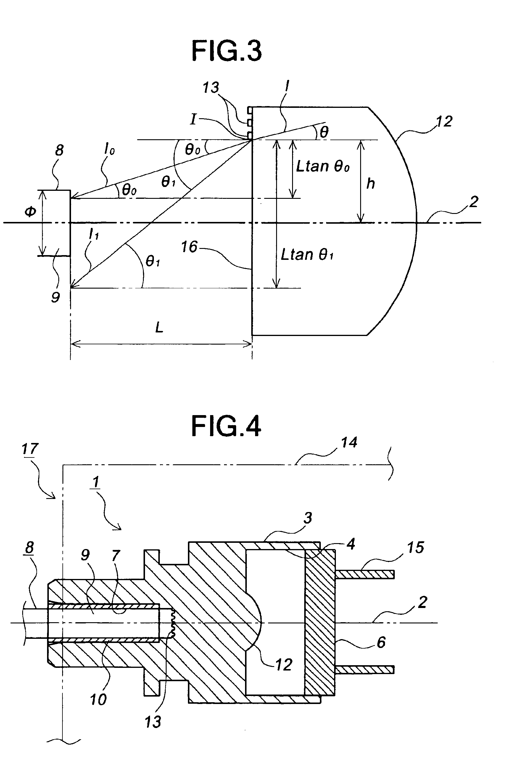
[0015]According to the above described optical module, the light-quantity damping means, the lens and the holder are formed so as to be integrated with each other, so that it is possible to improve assembling efficiency and reduce the number of parts. If the diffraction grating for preventing the high-order diffracted light beam from being coupled with the optical fiber is used as the light-quantity damping means, it is possible to simply and effectively prevent the occurrence of communication errors. In addition, if light reflected on the diffraction grating toward the photoelectric transfer element is treated as monitoring light for determining whether light is appropriately incident on the optical fiber, it is possible to more appropriately carry out optical communication. If the diffraction grating satisfies the above described expression (1), such an optical module capable of appropriately carrying out optical communication can be uniformly designed under conditions unified by expression (1), so that it is possible to more highly improve productivity.

Problems solved by technology

Therefore, in these optical modules, working and assembling efficiencies are not good.
However, since the light-quantity damping filter is separated from the holder and lens in the conventional optical module with the light-quantity damping filter, assembling efficiency is not good, and the number of parts is large.
Thus, there is a problem in that an optical module having a light-quantity damping filter can not be inexpensively produced, and effective means for solving this problem have not yet been proposed.

Method used


Image

  • Optical module and optical connector having same
  • Optical module and optical connector having same
  • Optical module and optical connector having same

Examples


Embodiment Construction

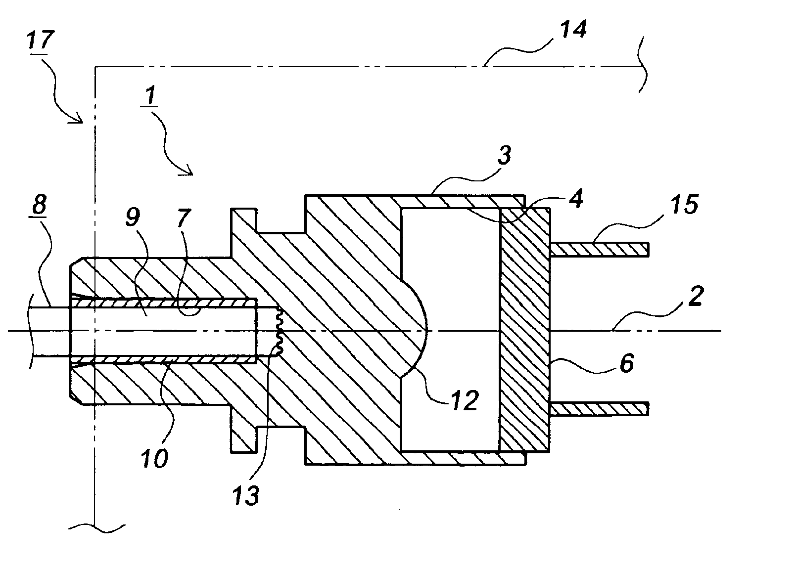
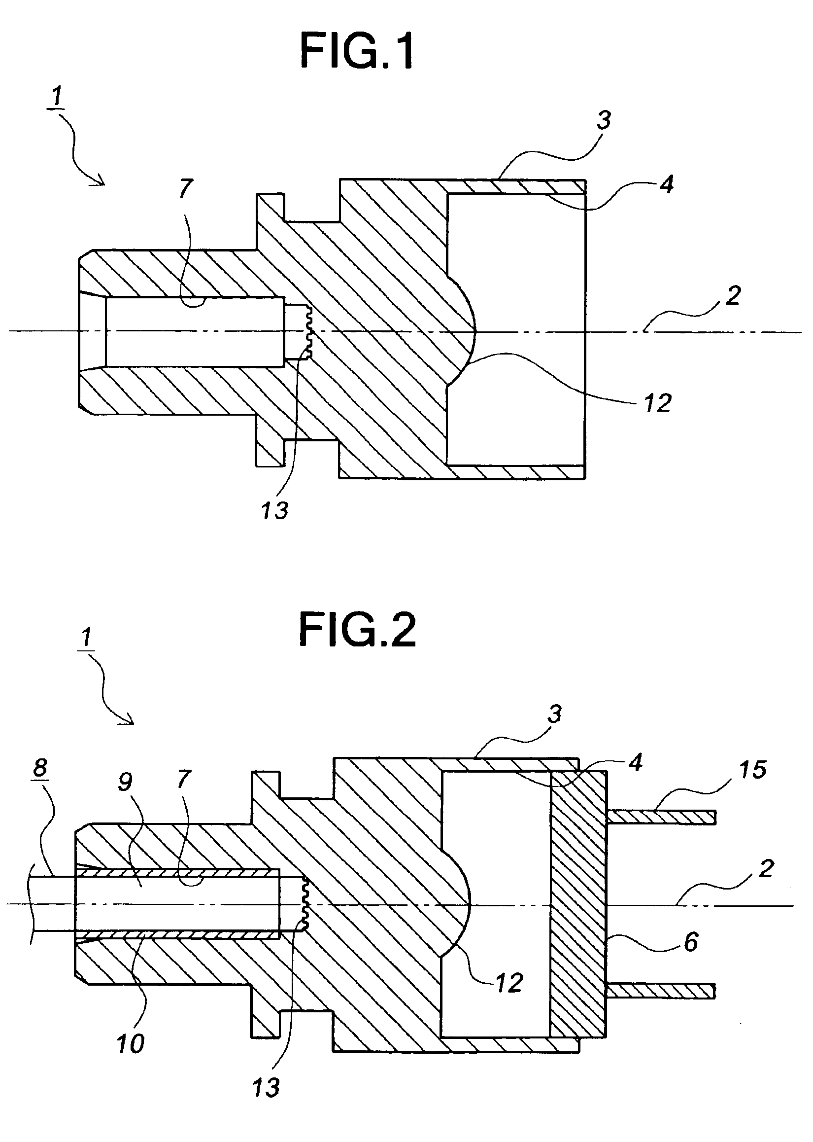
[0023]Referring now to the accompanying drawings, the preferred embodiment of an optical module and an optical connector having the same according to the present invention will be described below in detail.

[0024]As shown in FIG. 1, the preferred embodiment of an optical module 1 according to the present invention has a holder 3 extending along an optical axis 2. The holder 3 is formed by injection-molding a resin material, such as a phototransparent plastic (e.g., PEI (polyether imide), PC (polycarbonate) PMMA (polymethylmethacrylate)).

[0025]One end (the right side in FIG. 1) of the holder 3 in directions parallel to the optical axis 2 has a photoelectric transfer element package mounting hole 4 which extends along the optical axis 2. As shown in FIG. 2, a photoelectric transfer element package 6 housing therein a semiconductor light emitting element, such as a semiconductor laser, as an example of a photoelectric transfer element is designed to be mounted in the photoelectric trans...


PUM


Abstract

There is provided an optical module capable of improving assembling efficiency and reducing the number of parts to reduce production costs, and an optical connector having the same. The optical module has a holder 3, a lens 12 and a diffraction grating 13 for damping the quantity of light. The holder 3, the lens 12 and the diffraction grating 13 are formed of a resin material so as to be integrated with each other. The diffracting grating 13 is designed to prevent high-order diffracted light beams from being coupled with an optical fiber 8.

Description

BACKGROUND OF THE INVENTION[0001]1. Field of the Invention[0002]The present invention generally relates to an optical module and an optical connector having the same. More specifically, the invention relates to an optical module for high-speed and large-capacity optical communication using an optical fiber, and an optical connector having the same.[0003]2. Description of the Background Art[0004]In recent years, the request for optical fiber communication technology using optical fibers increases as the speed and capacity for data communication increase. A typical optical module for such optical fiber communication comprises: a photoelectric transfer element package (e.g., a package housing therein a semiconductor light emitting element, such as a semiconductor laser, or a semiconductor light receiving element, such as a photodiode); a ferrule for holding an end face of an optical fiber; a lens; and a holder for housing therein them.[0005]In such an optical module, a photoelectric tr...

Claims


Application Information

Patent Timeline
IPC IPC(8): G02B6/42G02B6/38H01S5/022
CPCG02B6/3865G02B6/4206
Inventor MORIOKA, SHIMPEI
Owner ENPLAS CORP
Learn More