Piezoelectric actuator, liquid jetting head and liquid jetting device using the same
a technology of actuator and liquid jetting head, which is applied in the direction of device details, device material selection, and device details, etc., can solve the problems that the ferroelectric material of the piezoelectric layer cannot arbitrarily combine the material of the buffer layer and the ferroelectric material of the piezoelectric layer, and achieves superior electro-mechanical transducing characteristics and piezoelectric characteristics, superior durability, and tight adhesion to the base layer
- Summary
- Abstract
- Description
- Claims
- Application Information
AI Technical Summary
Benefits of technology
Problems solved by technology
Method used
Image
Examples
embodiment 1
(Embodiment 1)
[0032]Embodiment 1 of the present invention relates to a piezoelectric actuator which uses a metal oxide in the bottom electrode, and which uses a relaxor ferroelectric material in the piezoelectric layer. The present embodiment is a piezoelectric actuator which is suitable for use in (for example) an ink jet recording head,
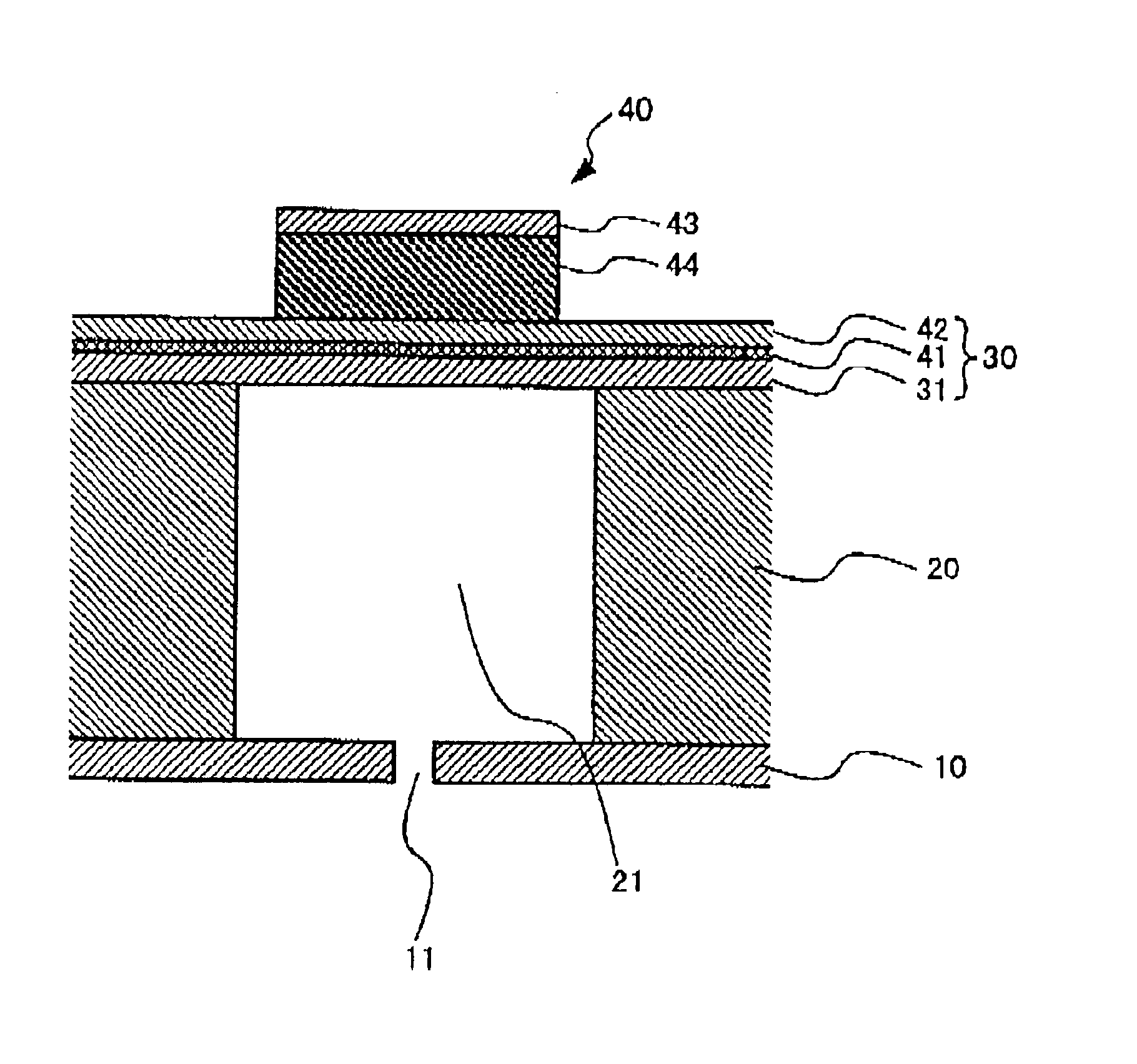
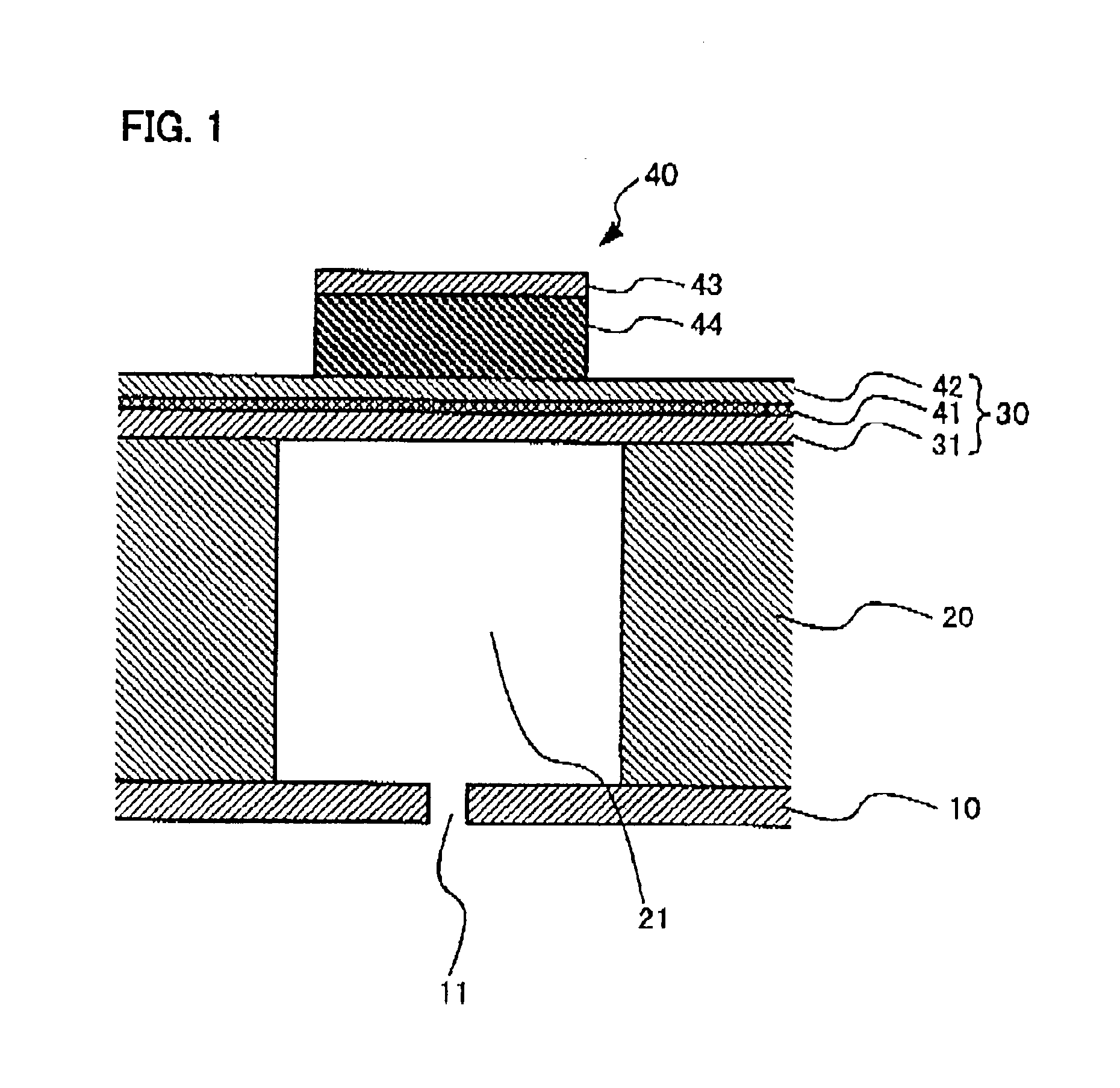
[0033]FIG. 1 shows a partial cross-sectional view which illustrates the piezoelectric actuator of Embodiment 1 and the layer structure of the ink jet recording head equipped with this piezoelectric actuator. FIG. 1 is an enlarged view of one of the ink jetting elements.
[0034]As is shown in FIG. 1, the piezoelectric actuator 40 is constructed by laminating a buffer layer 41, bottom electrode 42, piezoelectric layer 44 and top electrode 43 on an insulating film 31. In regard to the constituent elements that relate to the ink jet recording head, the device comprises a pressure chamber substrate 20 in which a pressure chamber 21 that holds the ink is fo...
example 1
[0059]A piezoelectric actuator was manufactured on the basis of Embodiment 1. In this example, a piezoelectric actuator was manufactured in which a laminated structure of strontium oxide, cerium oxide and yttrium-stabilized zirconium was formed as the buffer layer, a layer of strontium oxide with a (001) orientation was formed as the bottom electrode, and a piezoelectric layer consisting of a PMN0.7-PT0.3 relaxor dielectric material was grown on top of this bottom electrode. The thickness of the buffer layer was 100 nm, the thickness of the bottom electrode was 200 nm, and the thickness of the piezoelectric layer was 1000 nm.
[0060]FIG. 7 shows a θ·2θ XRD pattern diagram showing the results of X-ray diffraction analysis that was performed in order to investigate the orientation of the piezoelectric actuator of the present example. The piezoelectric layer shows a (001) orientation peak in the vicinity of 21.8°, and a (110) orientation peak in the vicinity of 31°. As is shown in FIG. 7...
embodiment 2
(Embodiment 2)
[0063]Embodiment 2 of the present invention relates to an ink jet recording head using the piezoelectric actuator of the present invention.
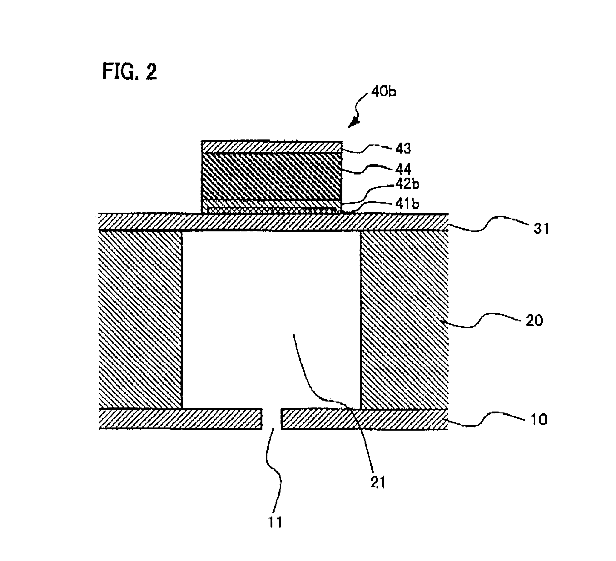
[0064]FIG. 5 shows an exploded perspective view of the ink jet recording head of the present embodiment. As is shown in FIG. 5, this ink jet recording head 1 comprises a pressure chamber substrate (silicon substrate) 20, a diaphragm 30 which is fastened to one side of the substrate 20, and which has the piezoelectric actuator 40 of the present invention (not shown in FIG. 5) formed on the back surface (the surface not shown in the figures), and a nozzle plate 10 which is fastened to the other side of the pressure chamber substrate 20. This head is constructed as an on-demand type piezo-jetting head. Either the piezoelectric actuator in which the piezoelectric layer is formed by a relaxor ferroelectric material as described in Embodiment 1, or the piezoelectric actuator in which the piezoelectric layer is formed by barium titanate as...
PUM
 Abstract
Description
Claims
Application Information
 - R&D
- Intellectual Property
- Life Sciences
- Materials
- Tech Scout
- Unparalleled Data Quality
- Higher Quality Content
- 60% Fewer Hallucinations
Browse by: Latest US Patents, China's latest patents, Technical Efficacy Thesaurus, Application Domain, Technology Topic, Popular Technical Reports.
© 2025 PatSnap. All rights reserved.Legal|Privacy policy|Modern Slavery Act Transparency Statement|Sitemap|About US| Contact US: help@patsnap.com


