Microwave medical treatment apparatus and method

a technology of microwave and medical equipment, applied in the field of microwave medical equipment and methods, can solve the problems of preventing damage to healthy tissue, obstructing the urinary tract, and surgical procedures for treating bph that are available but have potential side effects, so as to prevent damage to healthy tissue and quick

Inactive Publication Date: 2005-09-13
NASA
View PDF25 Cites 69 Cited by
  • Summary
  • Abstract
  • Description
  • Claims
  • Application Information

AI Technical Summary

Benefits of technology

[0032]The present invention provides procedures, apparatus, and computer simulations for radiating energy into body tissue that is especially effective for treating benign prostatic hyperplasia (BPH). A preferred embodiment of the present invention provides a separated microwave antenna system operable for producing a controllable heating profile in a tissue region. This embodiment may comprise one or more elements such as, for instance, a first microwave antenna positioned adjacent the tissue region and a second microwave antenna positioned adjacent the tissue region. The first microwave antenna and the second microwave antenna are spaced apart and are controllable to produ

Problems solved by technology

Hyperplastic enlargement of the prostate gland, or enlargement due to abnormal but benign multiplication of the cells thereof, often leads to compression of the urethra thereby resulting in obstruction of the urinary tract.
When treatment by drug therapy is not sufficiently effective, surgical procedures for treating BPH are available but have potential side effects.
General surgical risks apply such as anesthesia related morbidity, hemorrhage, coagulopathies, pulmonary emboli, electrolyte imbalance, and the like.
Other problems that may occur from surgical correction include cardiac complications, bladder perforation, incontinence, infection, urethral or bladder neck stricture, retention of prostatic chips, and infertil

Method used


Image

  • Microwave medical treatment apparatus and method
  • Microwave medical treatment apparatus and method
  • Microwave medical treatment apparatus and method

Examples


example 1

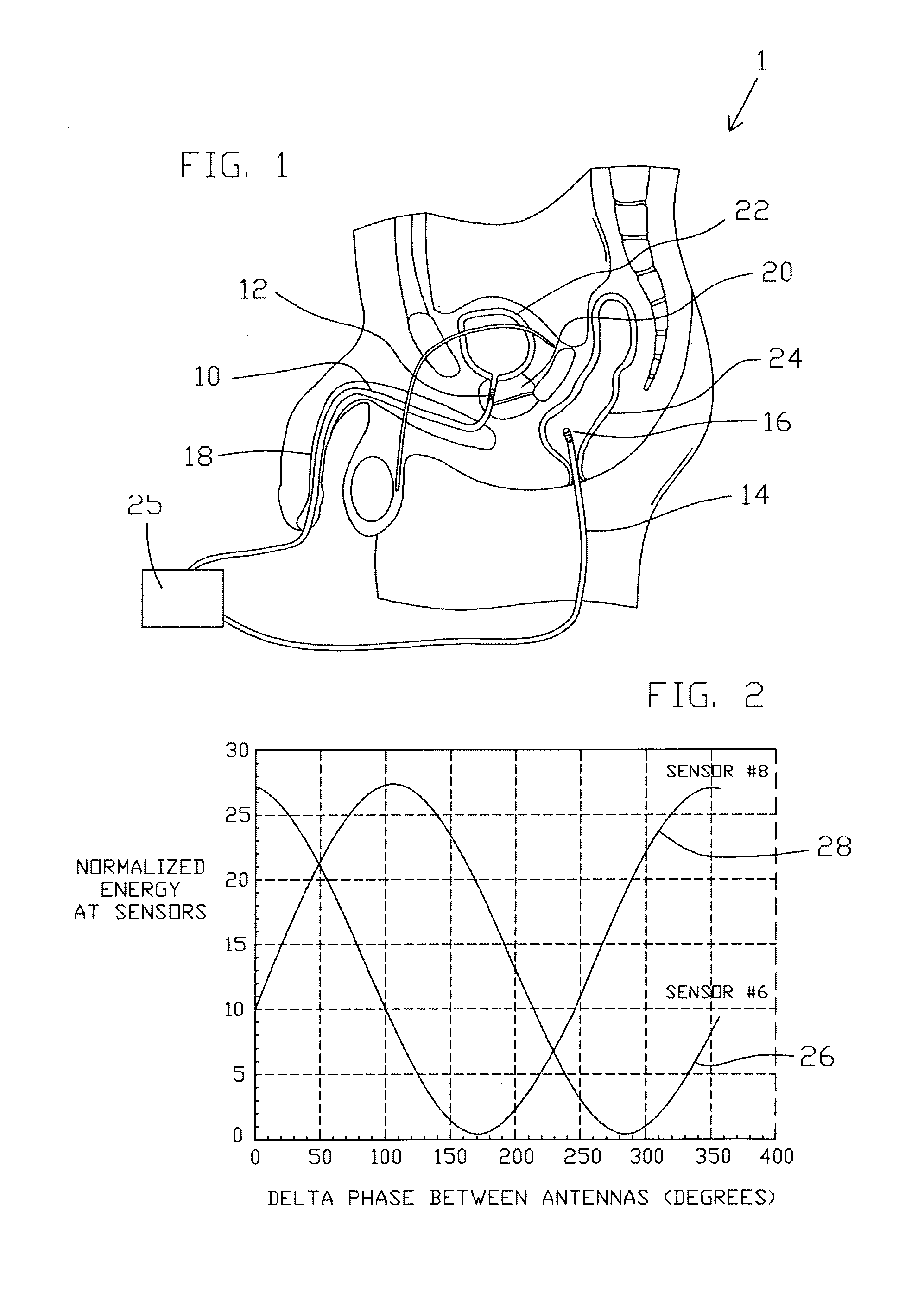
[0066]FIG. 2 shows computer projected results and / or laboratory testing results for a configuration whereby urethra antenna 12 and colon antenna 16 are separated by 3.8 centimeters and operating at 1.5 GHz. Numerous sensors may be utilized for laboratory testing and / or computer projections. In Example 1, sensor # 6 is located 20.5 mm from urethra antenna 12 and 14.5 mm from colon antenna 16. Sensor #8 is 23.5 mm from urethra antenna 12 and 11.5 mm from colon antenna 16. The spacing between sensors 6 and 8 is 3 mm. As can be seen in the data recorded in FIG. 2, the heating energy at each of the two sensor locations can vary from a maximum (the radiated energies from each antenna constructively add together in-phase) to a minimum (the radiated energies from each antenna destructively subtract from each other when 180 degrees out of phase) by simply adjusting the relative phase between antennas 12 and 16. The temperature variation at sensor 6 in response to changes in the phase differe...

example 2

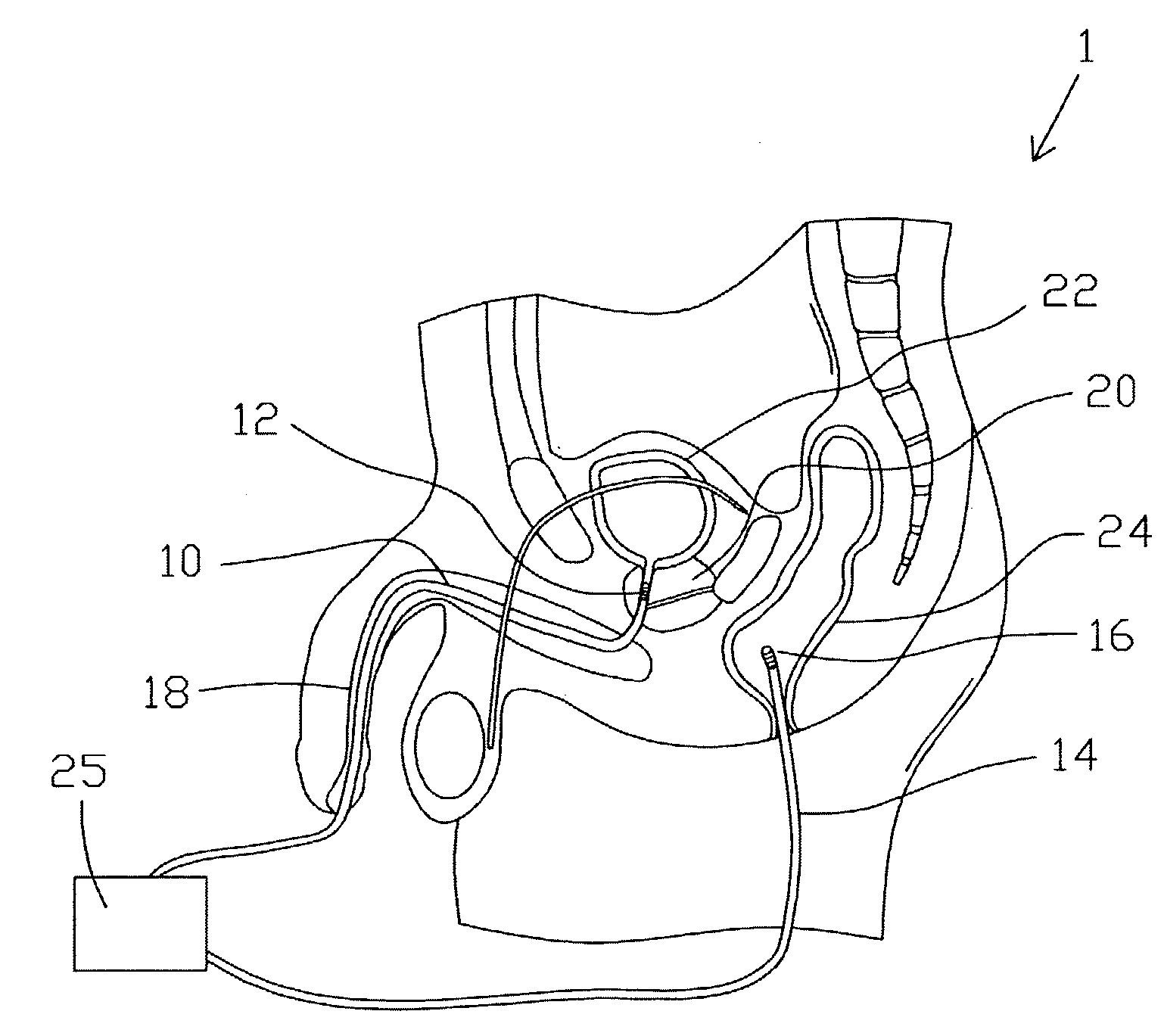
[0069]As an example of operation, and referring first to FIG. 1, antenna 12 in the urethra, and antenna 16 in the colon, are spaced apart by one wavelength, i.e., the frequency of the microwave power is adjusted such that the distance between urethra antenna 12 and colon antenna 16 is equal to one wavelength of the microwave signal to be transmitted by both antennas. One of the antennas is fed 180 degrees out of phase with the other. The frequency of operation is 2.5 gigahertz. As shown in FIG. 7, graph 30 shows the temperature variation versus distance between the two antennas. Urethra antenna 12 is referenced generally at position 34 as indicated in graph 30 and colon antenna 16 is referenced generally at position 36 in graph 30. In graph 30, a fairly uniform 22 degrees Centigrade temperature rise is produced in heated region 32, which is about 2 mm wide. This raised temperature is sufficient for ablating tissue and can be achieved between the two antennas without significant coll...

example 3

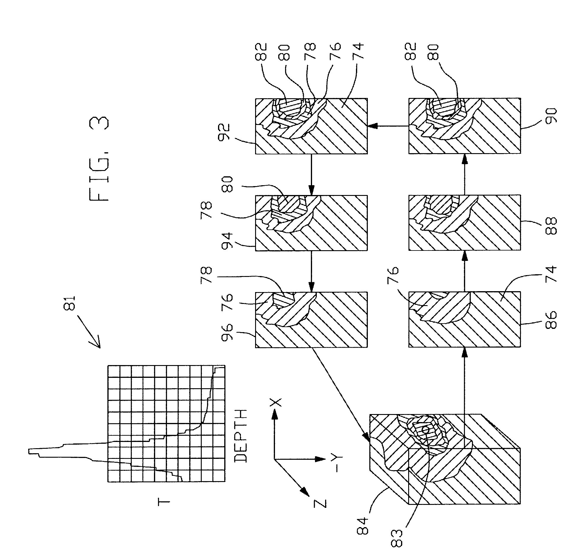
[0076]The basic advantages of multiple antennas over one antenna can be seen in comparing the results discussed in Examples 1 and 2 with the heating profile shown in FIG. 3. Because there is no cooling of the antenna, the maximum temperature increase is produced around the antenna as indicated at 83 in cube 84. As per graph 81, one antenna radiates with the maximum heat generated near the antenna. The heat falls off with the depth into the tissue. This also increases the cooling problem. Note that no cooling is applied to the antenna. By using suitable cooling and other means as taught in the parent cases to this application even with only one antenna, the tissues such as the urethra and / or colon tissues could be protected in the region surrounding the antenna to provide a useful heating profile for ablating some tissue and protecting tissue surrounding the antenna. As indicated in temperature versus depth graph 81, the maximum temperature increase is 34 degrees Centigrade. The shad...


PUM


Abstract

Methods, simulations, and apparatus are provided that may be utilized for medical treatments which are especially suitable for treatment of benign prostatic hyperplasia (BPH). In a preferred embodiment, a plurality of separate microwave antennas are utilized to heat prostatic tissue to promote necrosing of the prostatic tissue that relieves the pressure of the prostatic tissue against the urethra as the body reabsorbs the necrosed or dead tissue. By utilizing constructive and destructive interference of the microwave transmission, the energy can be deposited on the tissues to be necrosed while protecting other tissues such as the urethra. Saline injections to alter the conductivity of the tissues may also be used to further focus the energy deposits. A computer simulation is provided that can be used to predict the resulting temperature profile produced in the prostatic tissue. By changing the various control features of one or more catheters and the methods of applying microwave energy, a temperature profile can be predicted and produced that is similar to the temperature profile desired for the particular patient.

Description

[0001]This application is a continuation-in-part of U.S. application Ser. No. 09 / 746,533 filed Dec. 18, 2000, now U.S. Pat. No. 6,675,050 which is a divisional of U.S. application Ser. No. 09 / 511,961, now U.S. Pat. No. 6,289,249, filed Feb. 23, 2000 and issued Sep. 11, 2001.ORIGIN OF THE INVENTION[0002]The invention described herein was made in the performance of work under a NASA contract and is subject to the provisions of Section 305 of the National Aeronautics and Space Act of 1958, Public Law 85-568 (72 Stat. 435; 42 U.S.C. 2457).BACKGROUND OF THE INVENTION[0003]1. Field of the Invention[0004]The present invention relates to apparatus, methods, and computer simulations for radiating energy into body tissue and, more particularly, to a separated array of antennas and methods operable for highly selective heating of biological tissue.[0005]2. Background of the Invention[0006]Microwaves and other techniques have been used to necrose malignant, benign, and other types of cells and ...

Claims


Application Information

Patent Timeline
IPC IPC(8): A61F2/00
CPCA61B18/18A61B18/1815A61N5/045
Inventor ARNDT, G. DICKEYNGO, PHONG H.CARL, JAMES R.GEORGE, W. RAFFOUL
Owner NASA
Why Eureka
Try Eureka