[0014]In one aspect the invention encompasses providing a method and
system for the manufacture of misting manifold, as well as a unique misting manifold component. The inefficiencies of prior art misting
system construction are avoided by first producing an intermediate member, in place of the prior art riser construction, to receive one or more emitters and to be joined to the tubing. One or more intermediate members are joined to tubing to create a misting manifold. This method allows a butt or filet weld to be used, both welds being more amenable to use with the GTAW / TIG
welding of the automated orbital welder. This method and construction also allows for a more accurate construction and positioning of the intermediate members.
[0016]The shoulders of each intermediate member are joined to tubing by welding. Each shoulder is may be joined to tubing, preferably having substantially the same shape and wall thickness as the shoulder to ensure that both pieces are of about the same
heat capacity. Depending on the method of fabrication, the shoulder and tubing may have equivalent outside diameters. Alternatively the outside
diameter of the tubing may be slightly less than the inside
diameter of the shoulder, the
diameter of the axial channel, so that the tubing fits within the axial channel, either extending partially into the axial channel or completely through the length of the axial channel. Alternatively the inside diameter of the shoulder may be countersunk to allow the tubing to fit just within the axial channel, without extending further through the length of the axial channel. In all cases it is preferred that wall thickness of the shoulder and that of the selected tubing be matched to achieve equivalent heat capacities of the tubing and the shoulder. This equivalent
heat capacity of the two shoulders and the tubing allows for equal heating of both parts, resulting in an equal weld to both parts and avoiding damage from differential deformation or overheating of one of the two parts.
[0024]In a second embodiment two intermediate members are joined with tubing segments that extend therebetween. This embodiment may be combined with the first embodiment of joining intermediate members to tubing to create a misting manifold. With this second embodiment the shoulder may be formed to incorporate an annular step in the shoulder, the shoulder is countersunk, to serve as a stop to receive the tubing. The tubing in this embodiment is best not inserted into the intermediate member so far as to interfere with the communication of liquid between the
branch channel and the axial channel, countersinking the shoulder will prevent this. In this way the
insertion depth of the tubing can be predetermined and only partially inserted within the axial channel and then socket welded in place with TIG
orbital welding. With this construction there is therefore no need for the step of
puncturing the tubing through the
branch channel to allow liquid communication, because the tubing does not extend through the intermediate member.
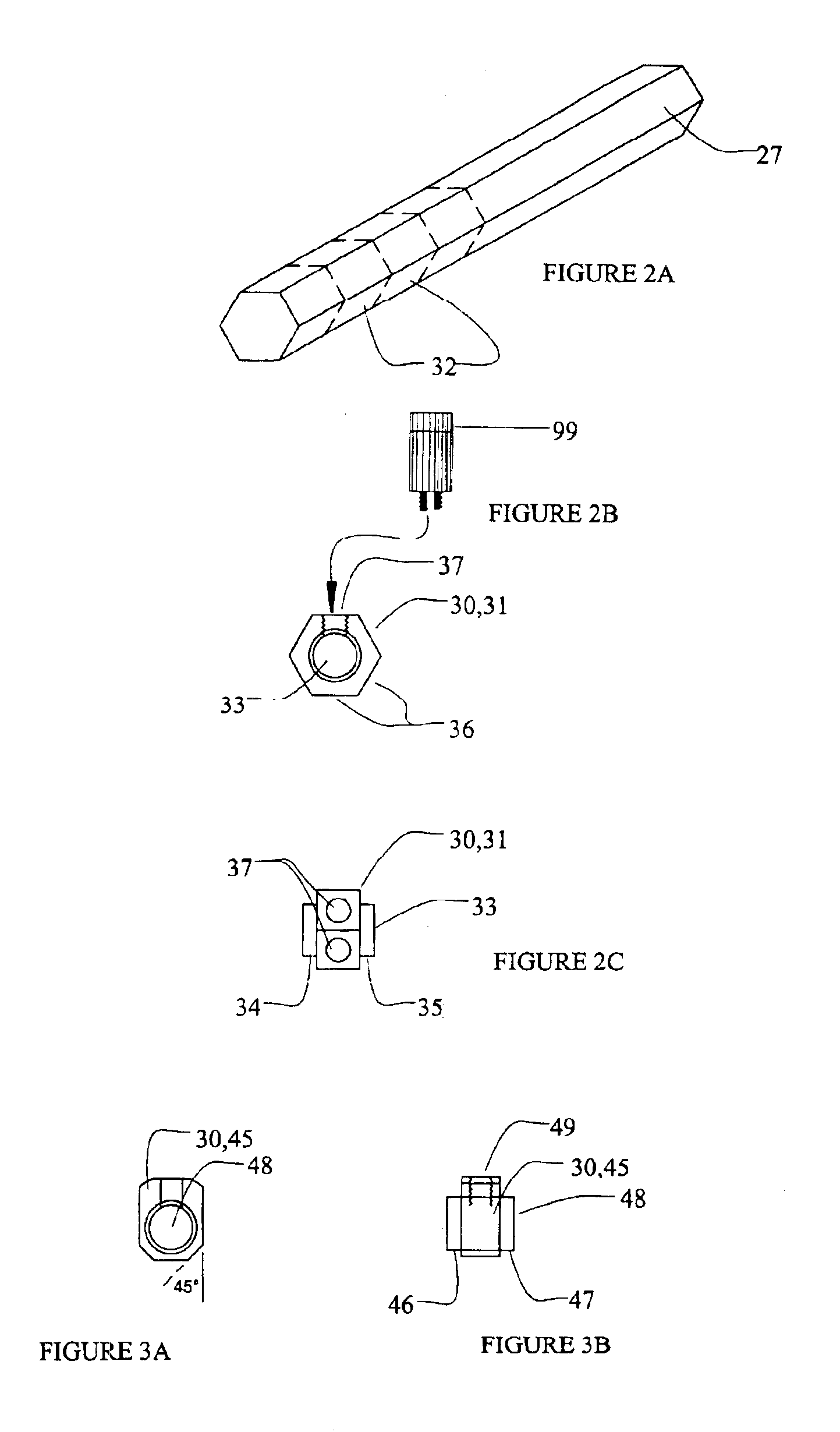
[0027]Emitters are fitted within the
branch channels. Emitters of various constructions and capacities, well known in the art may be used, depending on the spray pattern desired. Some emitters are designed to produce mist, others to produce
fog. The
system may be further extended by use of a flexible conduit have an
extender between the intermediate member and the emitter. In this manner misting manifold of any design may be efficiently and economically created by use of an automated orbital welder in a standardized manner to achieve consistent welds and exact angles in a misting manifold. An emitter
extender may be used, that is inserted into a branch channel. The emitter
extender consists of a male portion affixed to a branch channel and a female end adapted to receive an emitter.
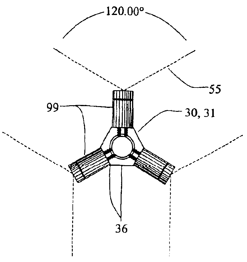
[0029]The number and positioning of the flattened surfaces and location of the axial channel on the intermediate member are specific to the application. The intermediate member may have one or more flattened surfaces to allow receive and securely seat an emitter, and the axial channel may be centrally located or offset from center. The flattened face formed to receive an emitter may further be parallel to the direction of the axial channel / tubing or it may be formed at an
oblique angle. The intermediate member may include a single surface, as in a tombstone type of intermediate member, or may include a multiplicity of surfaces. In the preferred embodiment for general use there are six equal surfaces provided surrounding a central axial channel to form a hex member. This shape allows for easy positioning of the emitters because the user can select a standard misting pattern in conjunction with the standard regularly spaced faces of the intermediate member. Emitters designed to produce a sixty degree mist pattern, for example, can be used with a hex shaped intermediate member to produce portions or all of a three hundred and sixty degree misting pattern. Each face, for example, may be equipped with an emitter having a sixty degree spray pattern to collectively achieve a three hundred and sixty degree spray pattern.

