Eureka AIR delivers breakthrough ideas for toughest innovation challenges, trusted by R&D personnel around the world.

Hybrid pneumatic-magnetic isolator-actuator

a hybrid, pneumatic-magnetic technology, applied in the direction of machine supports, shock absorbers, transportation and packaging, etc., can solve the problems of not providing force or position control, affecting the function of payload, actuators become stiff, etc., to reduce the stiffness of air springs, reduce isolation break frequency, and increase the added volume of air tanks

Inactive Publication Date: 2005-11-01
MOOG INC
View PDF9 Cites 22 Cited by
  • Summary
  • Abstract
  • Description
  • Claims
  • Application Information

AI Technical Summary

Benefits of technology

[0015]The invention disclosed is a compact and lightweight hybrid pneumatic-magnetic isolator-actuator capable of large force, substantial stroke and high bandwidth actuation with near frictionless operation and which behaves at high frequency like a very soft passive isolation mount.
[0016]The invention obtains superior low-frequency position control and simultaneous, superior base motion isolation. The invention controls the low-frequency forces applied to the payload according to a user-specified control law and sensor inputs, rather than simply in passive response to payload position. High frequency forces are still determined by base-relative position but are kept to low levels, similar to very soft passive isolators. The invention also allows for maintaining position control relative to an arbitrary reference, which may itself be moving in inertial space, rather than only relative to the base on which the payload is supported.
[0017]The invention combines pneumatic and magnetic forces on a single moving carriage assembly, comprised of a coaxially arranged piston and lower air bearing, journal shaft, coil and coil carrier structure. This carriage moves on air bearings relative to a frame or housing. The frame consists of a cylindrical sleeve surrounding the piston, a magnet body surrounding the coil, an upper air bearing surrounding the journal shaft, and a main housing supporting the cylindrical sleeve, magnet body, and upper air bearing. The outer diameter surface of the cylindrical sleeve serves as the journal for the lower air bearing. The construction of the invention thus allows for parallel pneumatic and magnetic forces to be developed between the carriage and frame in the form of a relatively lightweight and compact uniaxial strut. The frame of the strut attaches by a ball joint or universal joint to the supporting base and the carriage attaches by a similar ball joint or universal joint to the supported payload. The struts may be used in sets of six or more to completely support a payload in all degrees of freedom.
[0018]An important aspect of the invention when constructed in the form of a uniaxial strut is that bending loads are avoided. Substantially higher loads can be carried than that carried by those systems of the prior art which rely on the nesting of separate isolators and actuators.
[0019]The pneumatic piston provides static and low frequency actuation force for supporting the payload weight and for maintaining a desired payload position against low-frequency disturbances, such as inertial loads on the payload caused by aircraft maneuvering. Gas pressure, such as from air, nitrogen, or other gas, applied to the piston is controlled by a pressure servo. The pressure servo is comprised of a pneumatic servo-valve, a suitable drive amplifier and compensation for the valve, and a pressure transducer, all arranged in a feedback loop. The pressure servo allows the pressure on the piston, and thus the piston force, to be controlled by an input command signal. The invention thereby incorporates the capabilities of a pneumatic actuator with proportional control of its output force.
[0025]Furthermore, the isolator-actuator disclosed provides for near frictionless actuation and motion of the actuator carriage through the support of the carriage entirely on an air or gas film within the frame. In a preferred embodiment, the invention provides for the piston force to be exactly proportional to piston pressure, i.e. there being no friction drag between the piston and cylinder. Such behavior is ensured by the design of the frictionless piston. The frictionless piston is essential in order to use the magnetic actuator to correct for error in the pneumatic actuator. Frictionless behavior allows the instantaneous pneumatic force to be exactly measured by measuring the instantaneous gas pressure. Any friction would produce a difference between the true pneumatic force and that inferred from the product of measured pressure times known piston area.

Problems solved by technology

This is often detrimental to the function of the payload.
The nature of passive isolators is that they do not provide for force or position control that is necessary for payload stabilization when varying low frequency body forces are applied.
At the bandwidth limit, often set by dynamics of the payload, the actuators become stiff and unable to provide isolation to base motions of higher frequency.
Secondly, high fluid pressures, which allow wide bandwidth performance, require tight sliding seals to prevent leakage.
These seals inevitably introduce friction, which degrades high frequency isolation and introduces a deadband into low frequency position control.
In effect, seal friction produces dynamic forces on the payload, thereby defeating the desired isolation function.
Finally, hydraulic actuators are undesirable for use in vacuum because even very small oil leakage would cause contamination of any nearby equipment.
However, a dilemma faced in the use of pneumatic isolators as actuators is that the compressibility of the air in the isolator-actuator and pneumatic control valve severely limits the control bandwidth.
Additional control problems arise from the control system components necessary to drive the actuators.
Servo-valves used for either hydraulic or pneumatic control are commonly proportional spool valves, which always have a degree of friction and therefore produce hysteresis in the actuator control.
However the AS / VIS design has several limitations.
The voice coil actuators are quite heavy, being required to control the position of a large payload.
While producing excellent isolation, the system is too fragile to meet the crash load requirements for an airborne system, and thus requires a parallel system of slack tethers in order to meet airworthiness requirements.
Finally, the uncontrolled exhaust from the air bearings of the isolator-actuators render the system unsuitable for use in vacuum.
Other devices of the prior art have offered damping and vibration isolation with active control of the isolator damping characteristics, but they do not provide both actuation with high force capacity and the isolation characteristics of very soft passive mounts.
This device fails to provide the large actuation force and stroke capability and low break frequency isolation needed for stabilization of large airborne optical systems.
This device incorporates a spring or fluid system for load support and therein fails to provide the very low frequency vibration isolation and near frictionless actuation needed.
Additionally, actuation capability is limited to the force capability of the electric motor.

Method used


Image

  • Hybrid pneumatic-magnetic isolator-actuator
  • Hybrid pneumatic-magnetic isolator-actuator
  • Hybrid pneumatic-magnetic isolator-actuator

Examples


Embodiment Construction

[0039]Described in detail below is a compact and lightweight hybrid pneumatic-magnetic isolator-actuator. In the description, for purposes of explanation, numerous specific details are set forth in order to provide a thorough understanding of the present invention. It will be obvious, however, to one skilled in the art that the present invention may be practiced without these specific details. In other instances, well-known structures and devices are shown in simplified form in order to avoid obscuring the present invention. Additionally, though the embodiments described below refer to air as the gas used, any of various gases or combination of gases including nitrogen, argon, and helium could be used for effecting the isolation, pneumatic force, and coil cooling aspects of the invention.

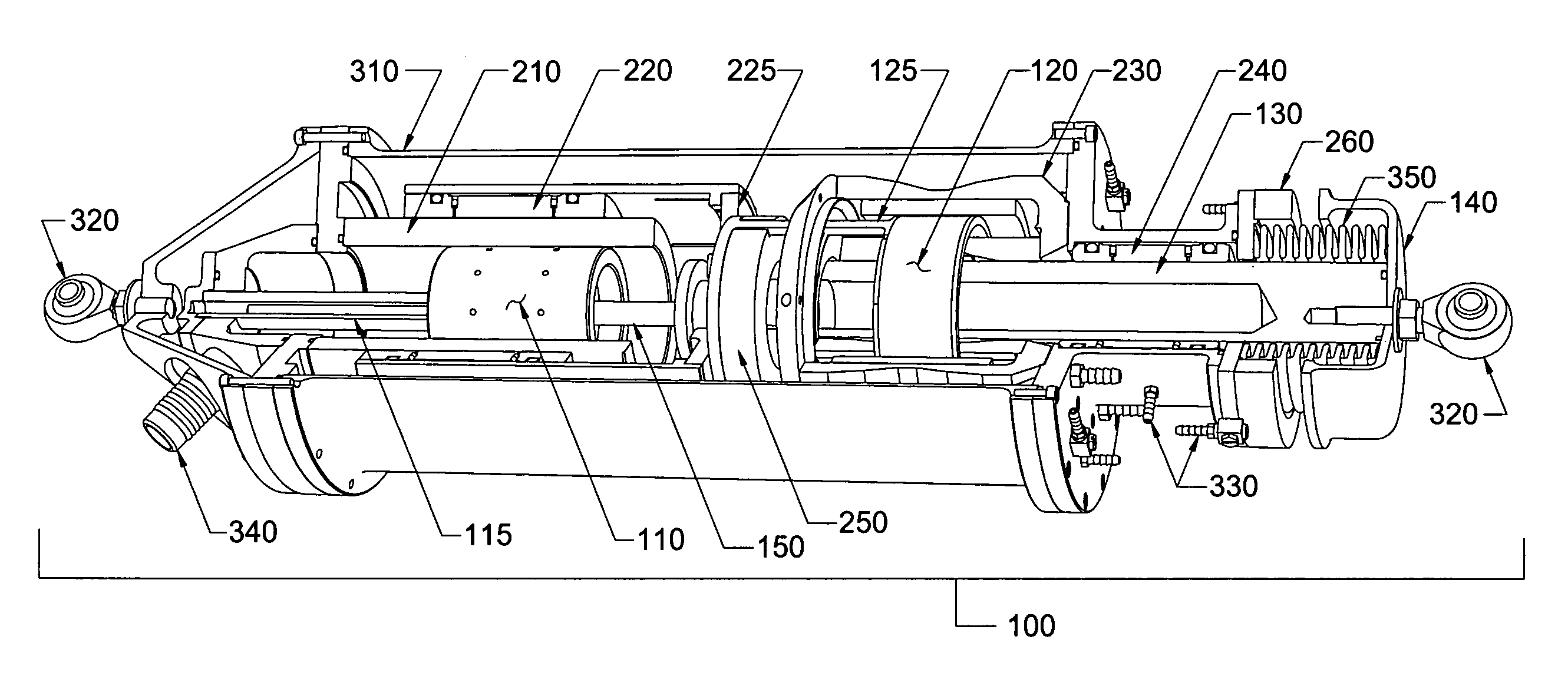
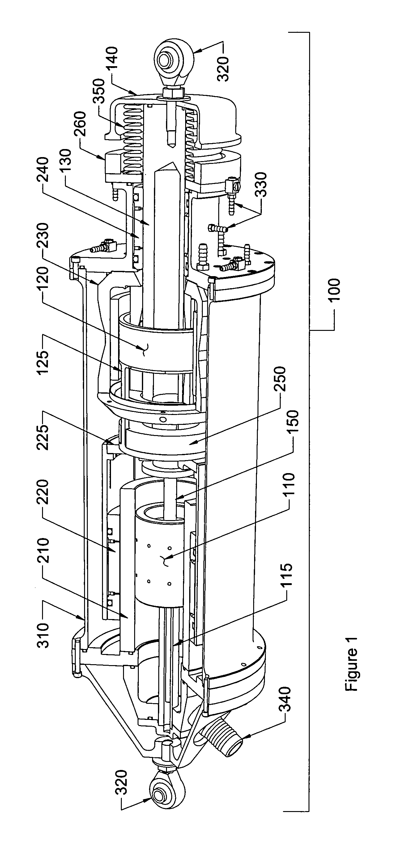
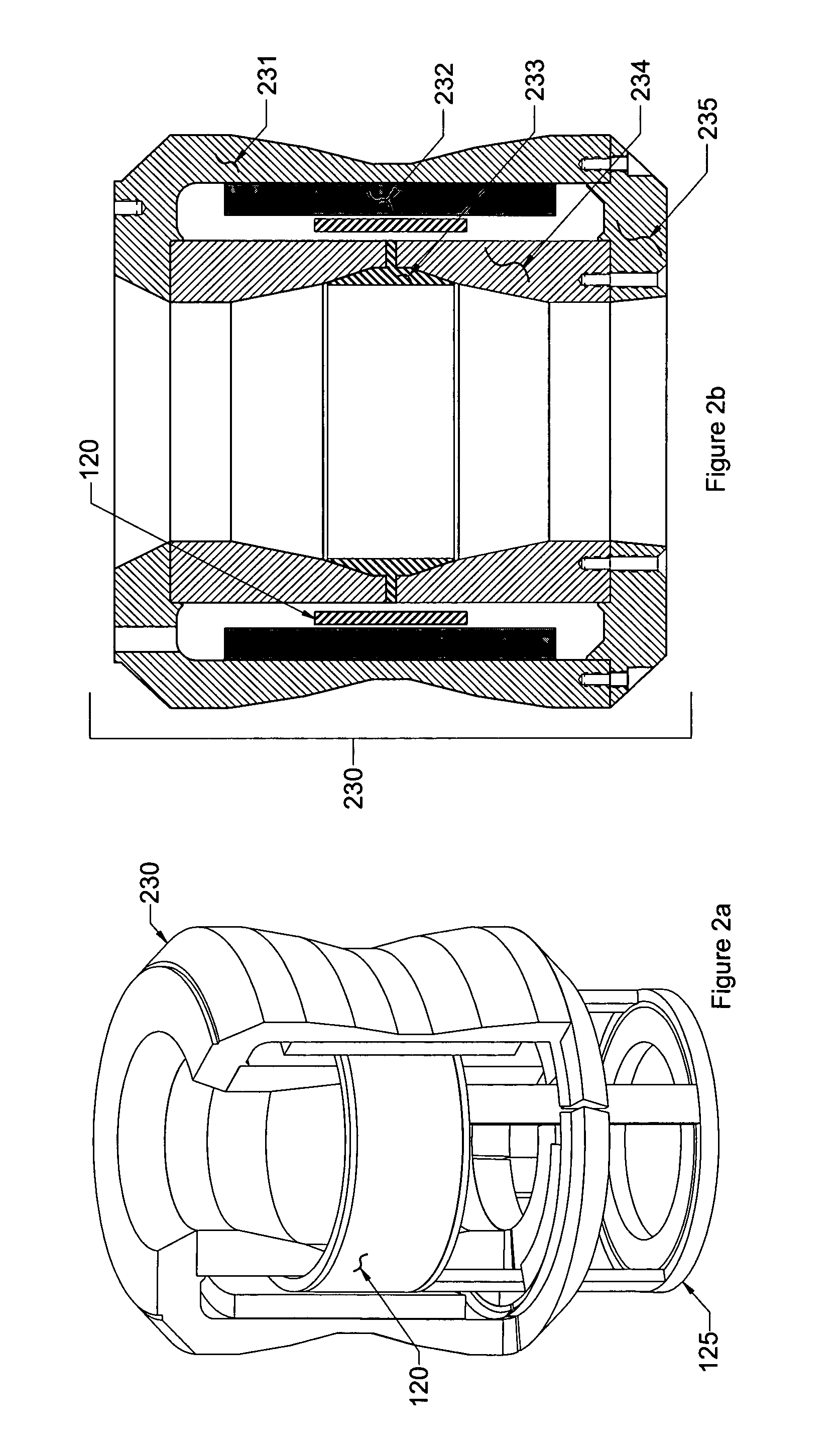
[0040]FIG. 1 shows a preferred embodiment of the invention where a cut away view of a hybrid pneumatic-magnetic isolator-actuator 100 is depicted. Within the isolator-actuator a single moving carria...


PUM


Abstract

The invention disclosed is a compact and lightweight hybrid pneumatic-magnetic isolator-actuator capable of large force, substantial stroke and bandwidth actuation with near frictionless operation and vibration isolation with very low break frequency. Pneumatic and magnetic forces are applied to a single carriage comprised primarily of a coaxially arranged air piston and coil. The carriage is driven relative to a frame or housing including an internally mounted cylindrical piston sleeve and magnetic actuator body. A combination of air bearings and air bearing piston construction provide for frictionless motion of the carriage relative to the frame. The pneumatic piston provides the actuation force for both static loads and low frequency dynamic loads. An integrally mounted sensor and control unit determine the pressure error resulting at the pneumatic piston. The control unit utilizes the pressure error to drive a high bandwidth magnetic actuation capability in parallel with the pneumatic actuation capability. An air tank of prescribed volume may be connected to the pneumatic piston for effecting a desired air-spring stiffness upon the isolator-actuator.

Description

STATEMENT REGARDING FEDERALLY SPONSORED RESEARCH[0001]This invention was made with U.S. Government support under a second level subcontract to Contract No. F29601-97-C-0001 awarded by the Department of the Air Force. The U.S. Government has certain royalty-free rights in this invention.BACKGROUND OF THE INVENTION[0002]The present invention relates to vibration isolators and position control actuators. More particularly, the present invention pertains to a compact hybrid pneumatic-magnetic isolator-actuator capable of large stroke, near frictionless operation, and high ratio of actuation force to weight.[0003]Passive isolation systems, composed of multiple passive vibration isolators, are commonly used for preventing vibration force input to a payload from a vibrating support base. Base motions of a frequency sufficiently higher than the break frequency of the isolation system (i.e. the natural frequency of the payload on the isolators) are significantly attenuated by the isolators a...

Claims


Application Information

Patent Timeline
Patent Type & Authority Patents(United States)
IPC IPC(8): F16F15/023F16F13/00F16F15/03H02K41/035F15B15/20F15B15/00
CPCF15B15/088F16F13/002F16F15/0232F16F15/03H02K41/0356
Inventor KIENHOLZ, DAVID A.
Owner MOOG INC
Why Eureka
Eureka Blog
Learn More