Swinging objective retarding immersion lens electron optics focusing, deflection and signal collection system and method

a technology of electron optics and immersion lens, which is applied in the field of scanning electron microscope, can solve the problems of limiting spatial resolution, disc confusion, and reliability problems in the engineering, manufacturing and production of integrated circuits, and achieves the effects of reducing specimen damage, high resolution, and large deflection field

Inactive Publication Date: 2005-11-01
HERMES MICROVISION TAIWAN
View PDF18 Cites 18 Cited by
  • Summary
  • Abstract
  • Description
  • Claims
  • Application Information

AI Technical Summary

Benefits of technology

[0010]A scanning electron microscope having a swinging objective retarding immersion lens electron optics focusing, deflection and signal capture system is disclosed herein that overcomes the drawbacks discussed above with regard to prior art objective lens. Specifically, the objective lens system of the invention converts a high energy primary electron beam to a lower energy electron beam at the specimen to minimize damage to the specimen. It also has relatively high resolution for clear examination of submicron features. Moreover, a scanning electron microscope, in accordance with the present invention, provides a relatively large deflection field to reduce the time to fully examine the specimen and includes a detection unit to more efficiently capture secondary electrons (SE) and backscattered electrons from the specimen (BSE).

Problems solved by technology

However, applying such a higher energy electron beam directly to the specimen is undesirable because it can cause damage to the specimen, which consequently leads to a reliability problem in the engineering, manufacturing and production of integrated circuits.
Using a low energy primary electron beam source avoids the reliability problem but limits the spatial resolution due to chromatic aberration of the objective lens and by electron-electron interaction within the beam.
This effect creates a disk of confusion at the image plane on the specimen and limits resolution of the system.
Second, it is difficult to achieve high secondary and backscattered electron capture efficiency with a low energy primary electron beam source.
If a multi-channel plate is used, there is a severe reliability problem due to contaminants collecting in the holes (channels) of the plate.
As stated above, spatial resolution of current low voltage scanning electron microscopes is essentially limited by the chromatic aberration of the objective lens and by the electron-electron interaction, or Boersch effect.
First, it is difficult to generate a large deflection field with these units, where the deflection field is the reachable area in the plane of the specimen over which the primary beam can be moved by the deflection system. As a consequence, only a relatively small portion of the specimen can be examined at a time without repositioning the specimen.
Second, because of the inherently small deflection field, the time required for inspecting, reviewing and measuring a specimen is substantially long. This results in increased engineering, testing, troubleshooting, and production costs, as well as an increase in integrated circuit turnaround time.

Method used


Image

  • Swinging objective retarding immersion lens electron optics focusing, deflection and signal collection system and method
  • Swinging objective retarding immersion lens electron optics focusing, deflection and signal collection system and method
  • Swinging objective retarding immersion lens electron optics focusing, deflection and signal collection system and method

Examples


Embodiment Construction

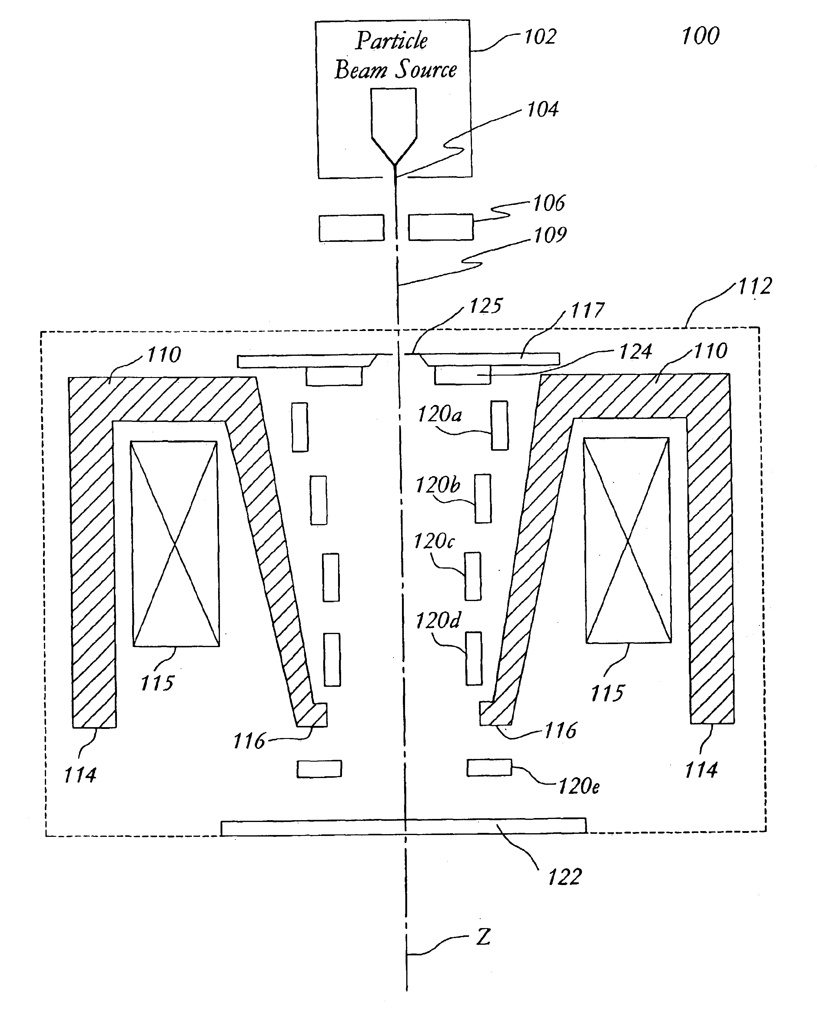
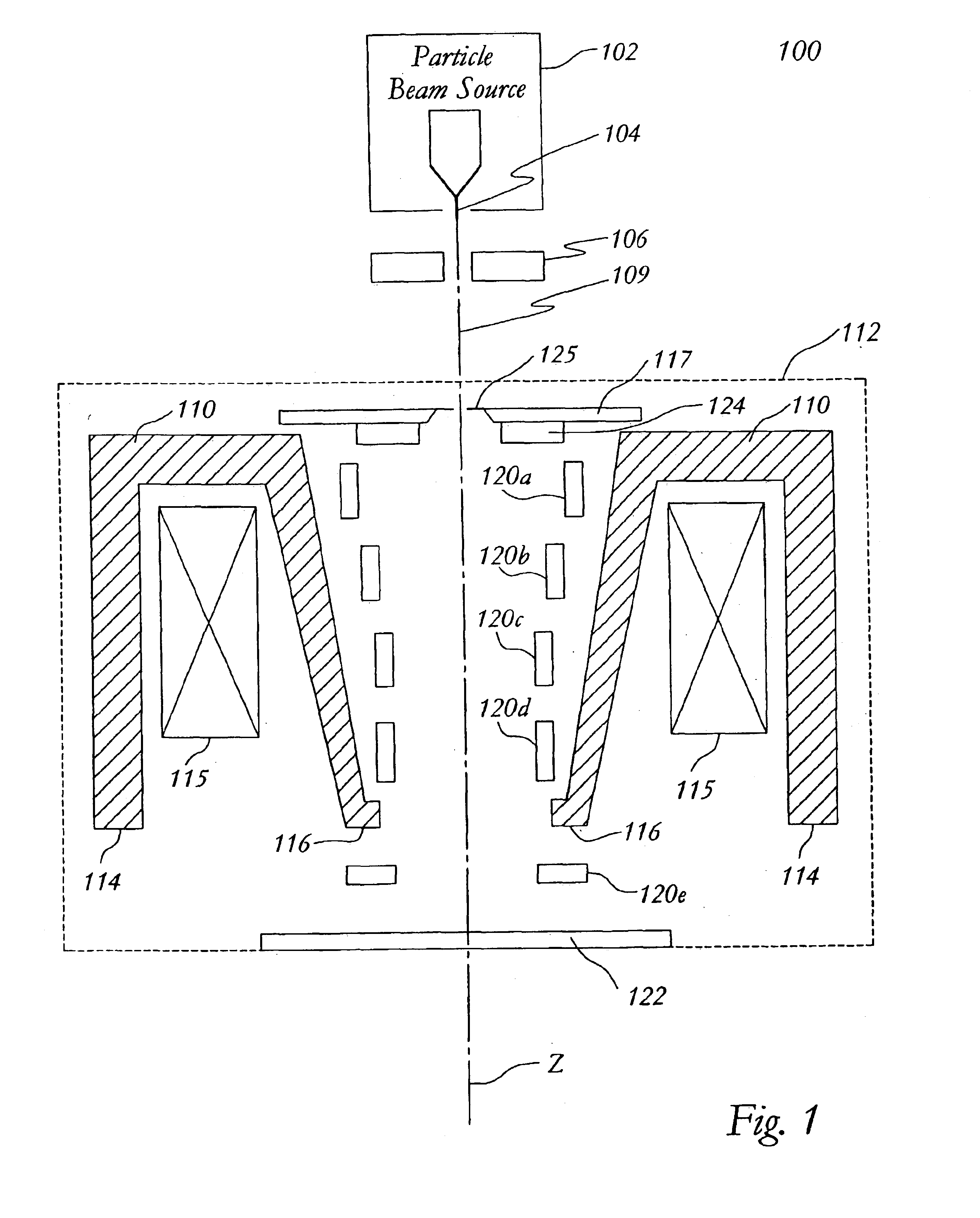
[0024]FIG. 1 illustrates an embodiment of a scanning electron microscope 100 in accordance with the present invention. In this embodiment, the scanning electron microscope 100 comprises a particle beam source 102 with virtual source point 104 (i.e., the effective source point for the particles), an anode 106, an objective lens system 112 having a magnetic lens therein and a plurality of deflection units 120a-120e. For reference purposes, a beam axis 109 is defined as the line connecting the particle beam source 102 to the specimen 122 and is designated the Z-axis, the X and Y axes defining a plane transverse to the Z-axis.

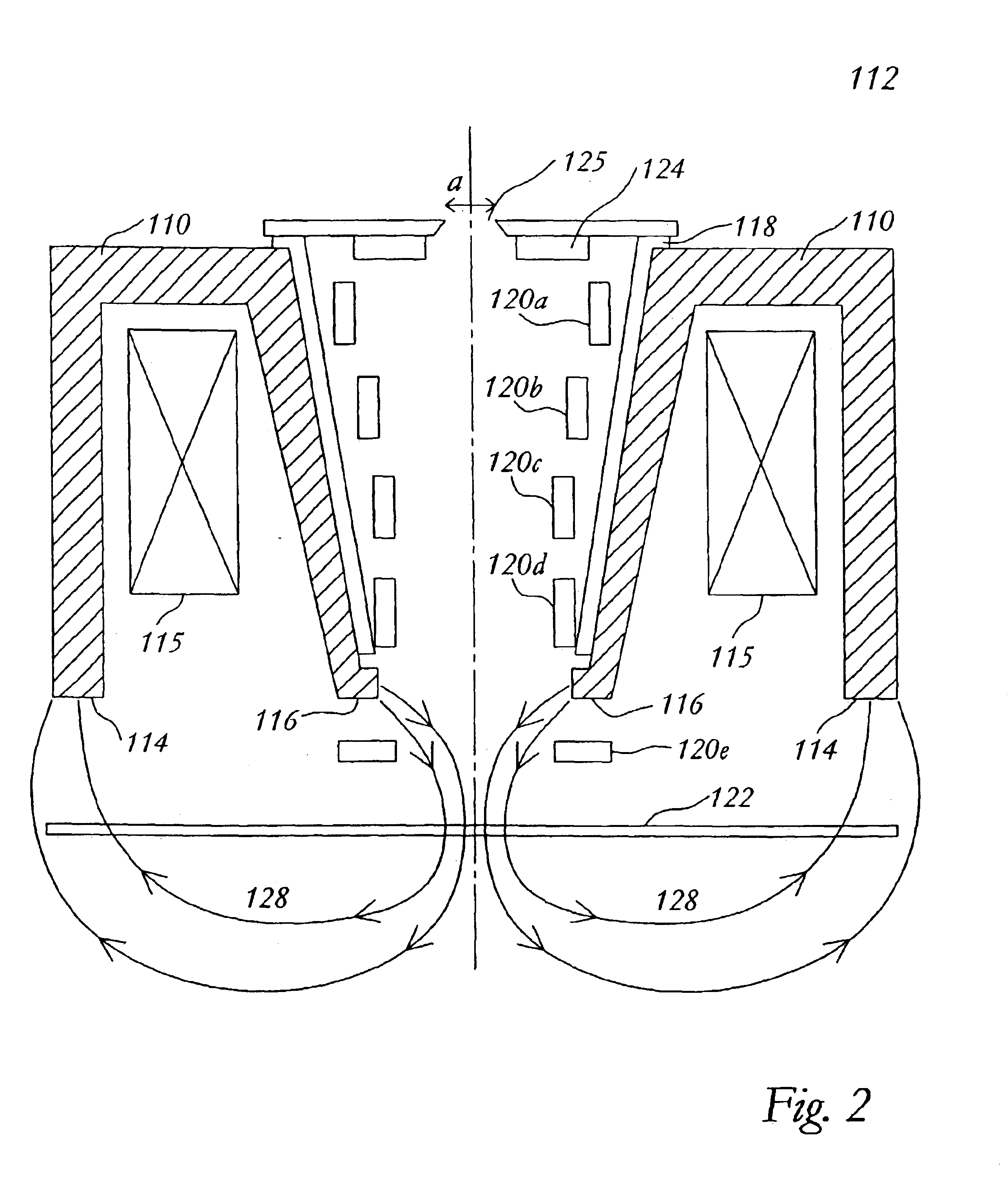
[0025]The magnetic lens includes material 110 and exciting coils 115 for providing magnetomotive force to a magnetic circuit having field lines through the magnetic material and between the pole faces 116 and 114. The central bore of the magnetic lens has the shape of a circular bucket which is axially symmetric about the Z-axis. At the place where the primary part...


PUM


Abstract

A swinging objective retarding immersion lens system and method therefore which provide a low voltage electron beam with high beam current, relatively high spatial resolution, a relative large scan field, and high signal collection efficiency. The objective lens includes a magnetic lens for generating a magnetic field in the vicinity of the specimen to focus the particles of the particle beam on the specimen, an electrode having a potential for providing a retarding field to the particle beam near the specimen to reduce the energy of the particle beam when the beam collides with the specimen; a deflection system including a plurality of deflection units situated along the beam axis for deflecting the particle beam to allow scanning on the specimen with large area, at least one of the deflection units located in the retarding field of the beam, the remainder of the deflection units located within the central bore of the magnetic lens; and a annular detection unit with a relatively small aperture, located underneath the primary beam define aperture, to capture secondary electron (SE) and backscattered electrons (BSE).

Description

RELATED U.S. APPLICATION[0001]This is a continuation of U.S. patent application Ser. No. 10 / 113,002, filed Mar. 28, 2002, now U.S. Pat. No. 6,605,805 entitled SWINGING OBJECTIVE RETARDING IMMERSION LENS ELECTRON OPTICS FOCUSING, DEFLECTION AND SIGNAL COLLECTION SYSTEM AND METHOD, which is a continuation of U.S. patent application Ser. No. 09 / 513,306, filed Feb. 25, 2000, now U.S. Pat. No. 6,392,231 entitled SWINGING OBJECTIVE RETARDING IMMERSION LENS ELECTRON OPTICS FOCUSING, DEFLECTION AND SIGNAL COLLECTION SYSTEM AND METHOD, commonly assigned and hereby incorporated by references for all purposes.FIELD OF THE INVENTION[0002]This invention relates generally to scanning electron microscopes, and in particular, to a swinging objective retarding immersion lens electron optics focusing and deflection system and method that can provides a high current low voltage primary electron beam, high resolution scanning, large scan field, and high signal capture efficiency.BACKGROUND OF THE INVEN...

Claims


Application Information

Patent Timeline
Patent Type & Authority Patents(United States)
IPC IPC(8): H01J37/28H01J37/10H01J37/141G01Q10/00G01Q30/02
CPCH01J37/141H01J37/28H01J2237/04756H01J2237/1035
Inventor CHEN, ZHONG-WEI
Owner HERMES MICROVISION TAIWAN
Why Eureka
Try Eureka