
Laminated chip electronic device and method of manufacturing the same

a technology of electronic devices and laminated chips, which is applied in the direction of fixed capacitor details, stacked capacitors, fixed capacitor terminals, etc., can solve the problems of poor yield and low manufacturing speed, and achieve the effects of improving yield, facilitating the performance of electroplating processes, and small equipment investmen

Active Publication Date: 2005-11-15
INPAQ TECH
View PDF2 Cites 16 Cited by
  • Summary
  • Abstract
  • Description
  • Claims
  • Application Information

AI Technical Summary

Benefits of technology

[0012]In the laminated chip electronic device and the method of manufacturing the same according to the present invention, the insulating layer is formed on the top, bottom, front and back surfaces of the body before the two electrodes are formed at the ends of the body. With such an arrangement, the subsequently-formed electrodes facilitate the performance of an electroplating process. The electroplating process performed for the electrodes of the present invention is suitable for use in any production lines without adjusting conditions of the electroplating process or a particular production line. Meanwhile, the step of forming the insulating layer can be performed for a batch of devices, and only small investment in equipment is required, so that a great throughput of the devices is obtained. In addition, the electrodes of the present invention can be made of materials with low prices.

Problems solved by technology

Unlike the conventional laminated chip electronic device in which the insulating layer is formed on the insulating parts of the device after the electrodes are formed, the laminated chip electronic device and the method of manufacturing the same of the present invention do not have the drawback that devices are covered with the insulating layer one by one, and each time only one surface of the device is covered with the insulating layer, resulting in low manufacturing speed and poor yields.

Method used


Image

  • Laminated chip electronic device and method of manufacturing the same
  • Laminated chip electronic device and method of manufacturing the same
  • Laminated chip electronic device and method of manufacturing the same

Examples


Embodiment Construction

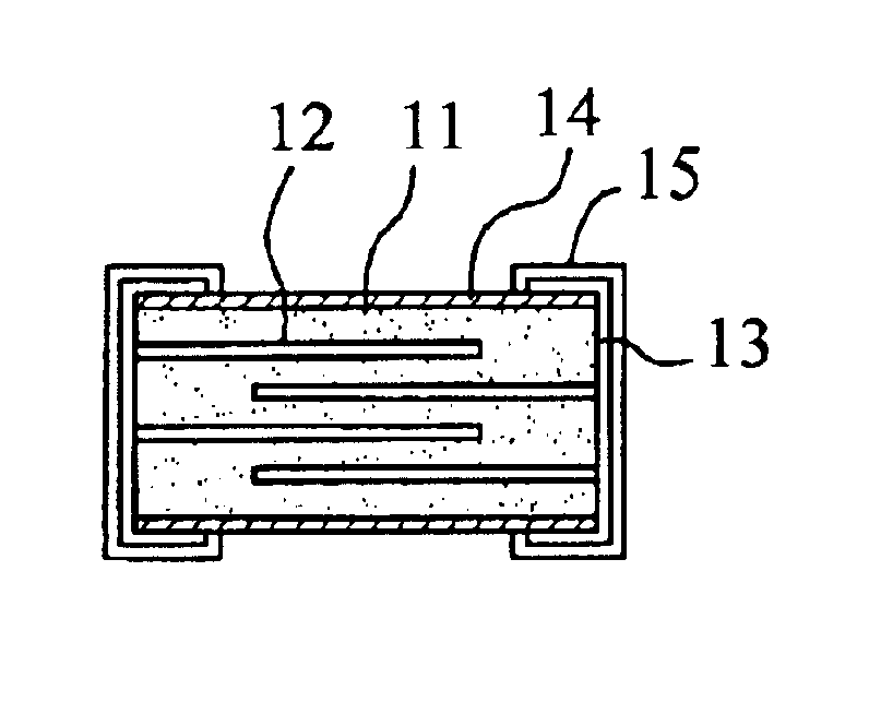
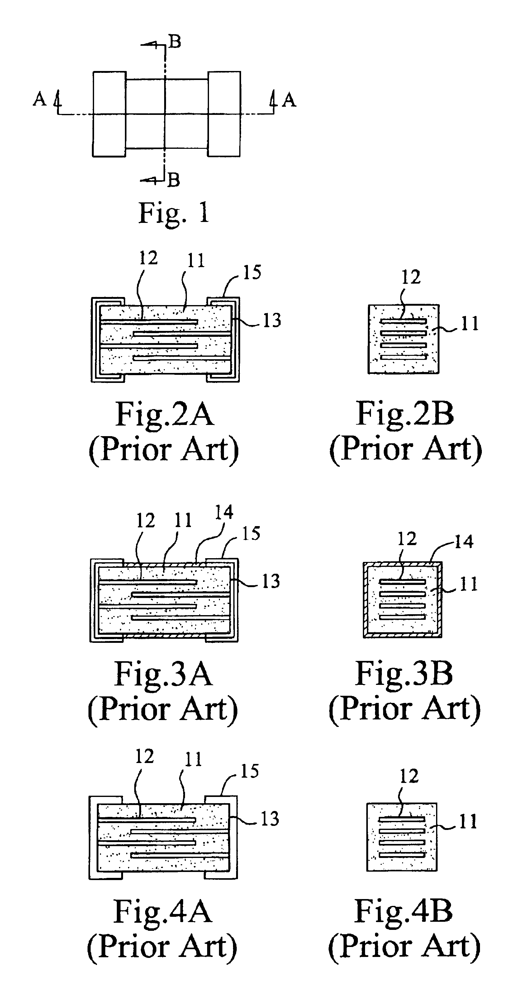
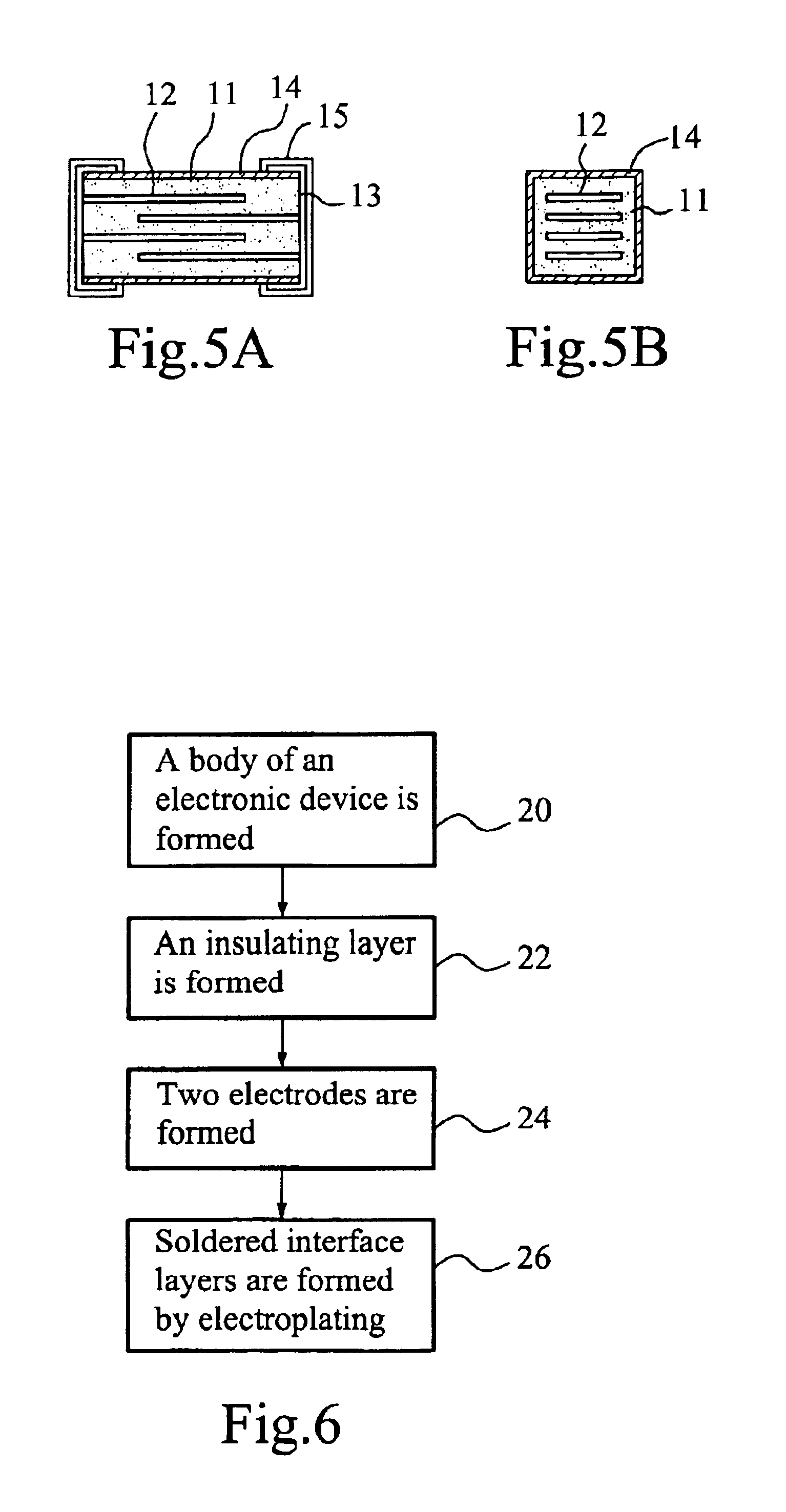
[0024]FIGS. 5A and 5B shows schematic, cross-sectional views of a laminated chip electronic device of the present invention taken along a line A—A and a line B—B of FIG. 1, respectively. The laminated chip electrode device of the present invention comprises a body 11, made of a non-linear resistive material and having a plurality of conductive layers 12, an insulating layer 14, formed on the top, bottom, front and back surfaces of the body 11, and two electrodes 13, formed at the ends of the body 11. The two electrodes 13 are electrically connected to the terminals of the conductive layers 12. The non-linear resistance coefficient material can be a zinc oxide or a strontium titanic acid.

[0025]FIG. 6 shows a flow chart of manufacturing a laminated chip electronic device according to the present invention. Referring to FIG. 6, a method of manufacturing a laminated chip resistive device according to the present invention comprises the following steps: forming a body which is made of a ...


PUM


Abstract

The present invention discloses a laminated chip electronic device and a method of manufacturing the same. In the laminated chip electronic device and the method of manufacturing the same according to the present invention, a body is made of a non-linear resistance coefficient material and has a plurality of conductive layers formed therein; an insulating layer is formed on the top, bottom, front and back surfaces of the body; and two electrodes are formed at the two ends of the body and electrically connected to the terminals of the conductive layers, respectively. Furthermore, in the present invention, two soldered interface layers are formed on the two electrodes, respectively.

Description

BACKGROUND OF THE INVENTION[0001]1. Filed of the Invention[0002]The present invention relates to a laminated chip electronic device and a method of manufacturing the same. More particularly, the present invention relates to a laminated chip electronic device with a non-linear resistance coefficient and a method of manufacturing the same, wherein an insulating layer is first formed on the top, bottom, front and back surfaces of a body of the laminated chip electronic device, so that subsequently formed electrodes are electroplated easily.[0003]2. Description of the Related Art[0004]Currently, laminated chip electronic devices (such as the one shown in FIG. 1) are widely used. Materials used for manufacturing the laminated chip electronic devices are various. Among these materials, non-linear resistance coefficient materials for manufacturing the bodies of the laminate chip electronic devices become more and more popular. The laminated chip electronic devices manufactured finally are ...

Claims


Application Information

Patent Timeline
IPC IPC(8): H01L23/48H01G4/224H01G4/232H01G4/30
CPCH01G4/224H01G4/232H01G4/30
Inventor LIU, SHIH-KWAN
Owner INPAQ TECH
Learn More