Process for producing aligned carbon nanotube films

a carbon nanotube and film technology, applied in the direction of catalyst activation/preparation, physical/chemical process catalysts, metal/metal-oxide/metal-hydroxide catalysts, etc., can solve the problems of difficult to realize inexpensive production of large-area, aligned carbon nanotube films that are suitable, and the obtained nanotubes

Inactive Publication Date: 2005-11-22
MITSUBISHI GAS CHEM CO INC
View PDF13 Cites 72 Cited by
  • Summary
  • Abstract
  • Description
  • Claims
  • Application Information

AI Technical Summary

Benefits of technology

[0008]The present invention has been accomplished under these circumstances and has an object providing a process in which a substrate for forming a film of carbon nanotubes having small outside diameter and aligned is prepared by a simple method and which can produce a large-area and uniformly aligned carbon nanotube film.

Problems solved by technology

However, many of the carbon nanotubes obtained by these methods have no orientation and it has been impossible to form carbon nanotube bundles or films.
However, these methods have problems such as the cumbersome steps required to prepare substrates for forming aligned carbon nanotubes and the limited area over which aligned carbon nanotubes can be formed and, hence, it has been difficult to realize inexpensive production of large-area, aligned carbon nanotube films that are suitable for the above-listed applications.
What is more, those methods can only generate an aligned film of thick carbon nanotubes greater than 20 nm in outside diameter.
There has also been disclosed a method comprising the steps of coating a substrate with catalyst particles, thermally decomposing a hydrocarbon on the substrate and shaving off the generated carbon nanotubes (JP 2001-80912 A) but this process is not capable of producing aligned carbon nanotube films.

Method used


Image

  • Process for producing aligned carbon nanotube films
  • Process for producing aligned carbon nanotube films
  • Process for producing aligned carbon nanotube films

Examples


example 1

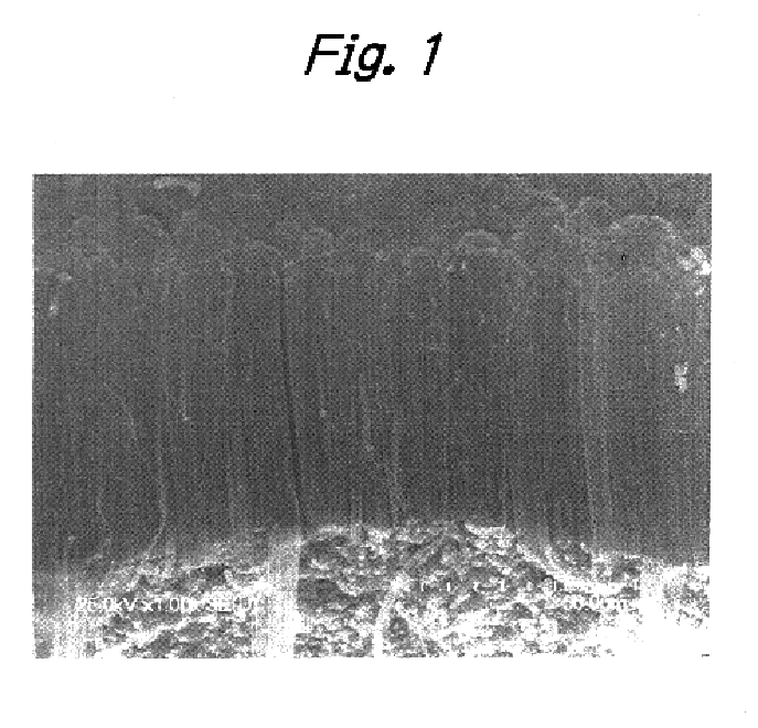
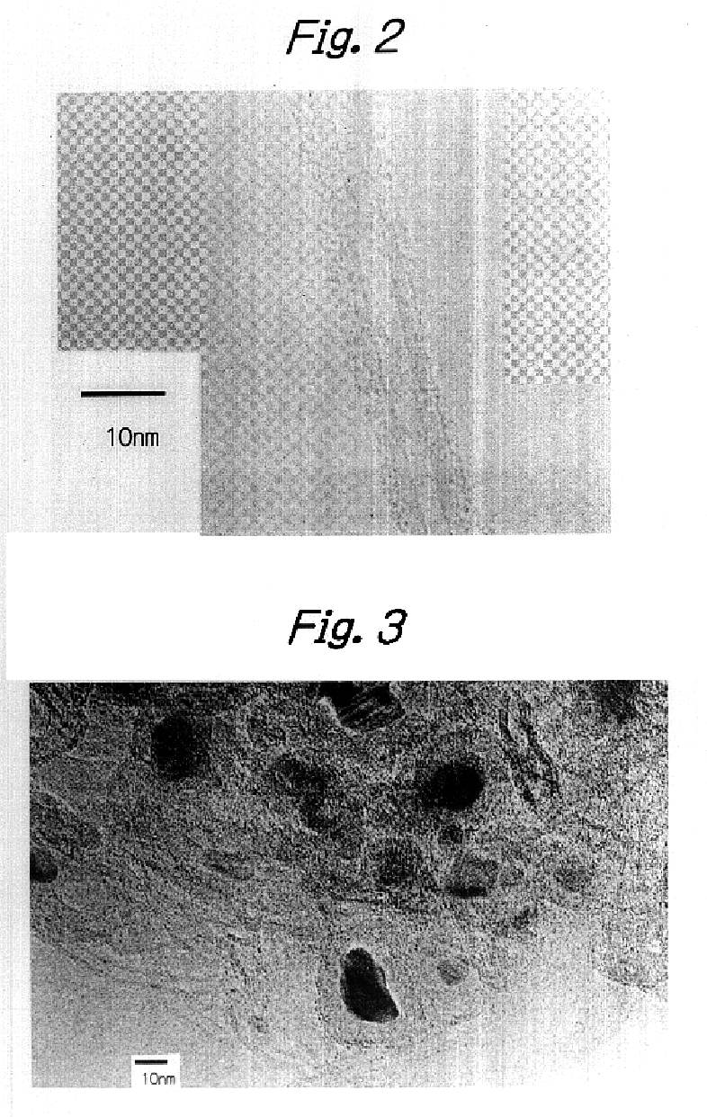
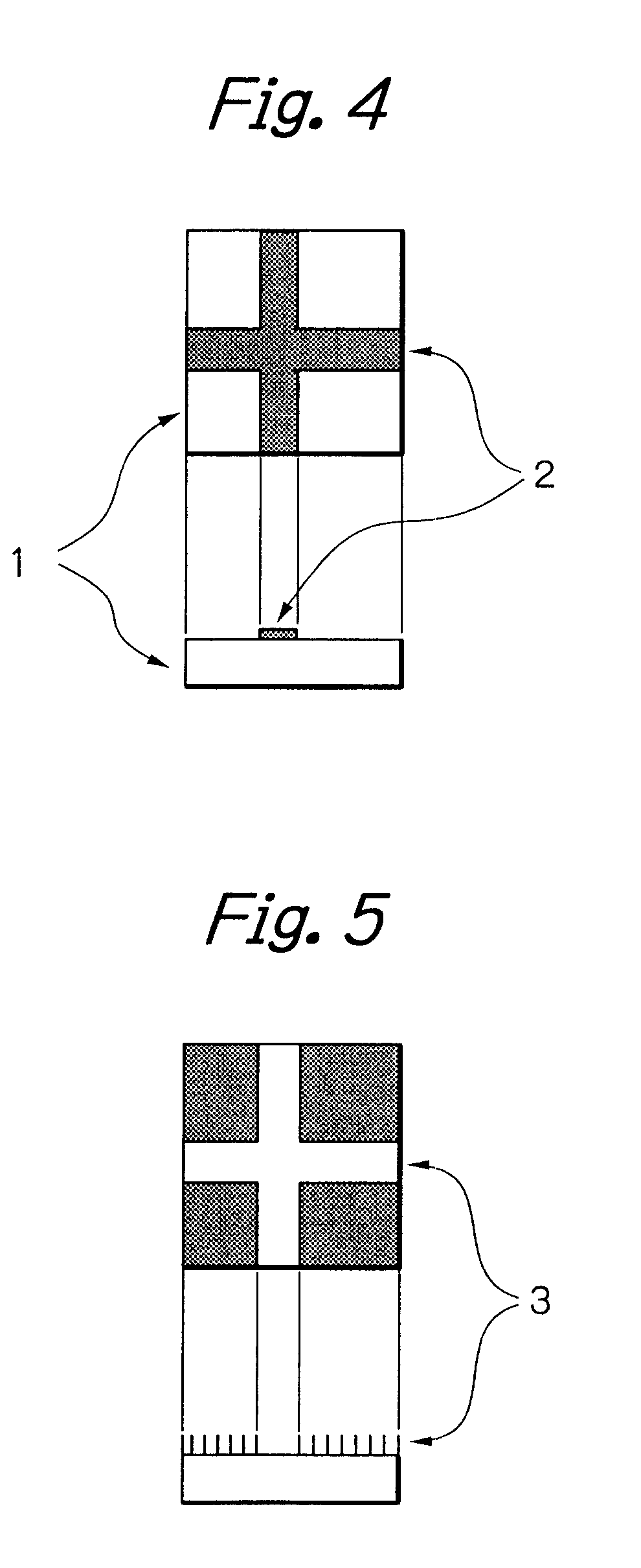
[0036]A square silica-alumina substrate consisting of 25% silica and 75% alumina and measuring 2 mm thick and 75 mm on each side was deposited with aluminum by vacuum deposition. The deposited aluminum film was 0.5 μm thick. The substrate was then dipped for 2 hours in an aqueous solution of cobalt nitrate at a concentration of 0.2 mol / L. The substrate was recovered from the aqueous solution and calcined in air at 400° C. for 3 hours. After the calcining, the substrate was placed horizontally in a tubular quartz glass furnace (diameter is 35 mm) with the aluminum-deposited side facing up. The tubular furnace was heated up to 700° C. with argon being blown horizontally at a flow rate of 1000 cm3 / min under atmospheric pressure (0.1 MPa). Subsequently, with the temperature of 700° C. being kept, a mixture of propylene (300 cm3 / min) and argon (1000 cm3 / min) was blown into the tubular furnace. After flowing of the propylene / argon mixed gas for 20 minutes, the gas supply was switched to a...

example 2

[0038]A square alumina substrate measuring 2 mm thick and 75 mm on each side was deposited with aluminum by vacuum deposition. The deposited aluminum film was 0.7 μm thick. In the next step, there was prepared a mixed solution containing cobalt nitrate and nickel nitrate each at a concentration of 0.1 mol / L; an aqueous solution of sodium hydrogencarbonate (0.4 mol / L) was added to the mixed solution and the mixture was stirred for 30 minutes. Thereafter, the mixture was decanted and the resulting sol was applied with a brush onto the aluminum deposited side of the substrate. The substrate was then dried at 100° C. for 30 minutes. The same procedure of coating and drying operations was repeated twice before the substrate was calcined in air at 400° C. for 3 hours. After the calcining, the substrate was placed horizontally in a tubular quartz glass furnace (diameter is 35 mm) with the aluminum deposited side facing up. The tubular furnace was heated up to 700° C. with argon being blown...

example 3

[0040]A square silica-alumina substrate measuring 2 mm thick and 30 mm on each side was heated in air at 400° C. for 3 hours and then deposited with aluminum by vacuum deposition. The deposited aluminum film was 0.2 μm thick.

[0041]An aqueous solution of cobalt nitrate (0.3 mol / L) was cooled to 10° C. and to the stirred solution, 0.2 ml of 29% aqueous ammonia was added. Blue cobalt hydroxide particles were generated in the purple aqueous solution to form a suspension. After stirring the suspension for 10 minutes, the previously prepared aluminum-deposited substrate was dipped in the stirred suspension for 10 minutes.

[0042]The substrate was recovered from the suspension and calcined in air at 400° C. for 3 hours.

[0043]After the calcining, the substrate was placed horizontally in a tubular quartz glass furnace (diameter is 35 mm) with the aluminum-deposited side facing up. The tubular furnace was heated up to 700° C. with argon being blown horizontally at a flow rate of 360 cm3 / min und...


PUM

PropertyMeasurementUnit
sizeaaaaaaaaaa
temperatureaaaaaaaaaa

Abstract

A process for producing aligned carbon nanotube films, wherein a carbon compound is decomposed using a substrate that is coated with an element having no catalytic ability by itself and which loads a metallic element having catalytic ability or a compound thereof, thereby forming a film of fine carbon nanotubes on the surface of the substrate which are aligned in a direction perpendicular to the substrate.

Description

BACKGROUND OF THE INVENTION[0001]This invention relates to a process for producing an aligned carbon nanotube film comprising a multiple of aligned carbon nanotubes. The process of this invention is suitable for producing aligned carbon nanotube films that can be used in many applications including electron emitters, cell electrodes, gas separating membranes, sensors and storage of energy.[0002]The carbon nanotube, first discovered by Sumio Iijima in 1991 [Nature, 354, pp. 56-58 (1991)], is a very slender, hollow tubular carbon material which is generally 1-100 nm in diameter and 1-100 μm long.[0003]It has been proposed with great expectation that the carbon nanotube be used in a wide range of applications including electron emitters, cell electrodes, gas separating membranes, sensors and storage of energy. When carbon nanotubes are to be used in these applications, they are preferably shaped to be aligned in one direction so that they can be assembled into an apparatus effectively ...

Claims


Application Information

Patent Timeline
Patent Type & Authority Patents(United States)
IPC IPC(8): D01F9/127D01F9/12B01J23/75B01J23/755B01J35/02B01J37/02B01J37/03C01B31/02C30B29/66
CPCB82Y30/00B82Y40/00C01B31/0233D01F9/127C01B2202/08Y10S977/842C01B32/162
Inventor SOMEYA, MASAOFUJII, TAKASHIHIRATA, MASUKAZUHORIUCHI, SHIGEO
Owner MITSUBISHI GAS CHEM CO INC
Why Eureka
Try Eureka