Low-friction sliding mechanism

a sliding mechanism and low friction technology, applied in the direction of sliding contact bearings, crankshafts, mechanical equipment, etc., can solve the problems of low friction coefficient and insufficient low friction coefficient of dlc material, and achieve low friction coefficient, low friction performance, and high abrasion resistance

Active Publication Date: 2005-11-29
NISSAN MOTOR CO LTD +1
View PDF2 Cites 36 Cited by
  • Summary
  • Abstract
  • Description
  • Claims
  • Application Information

AI Technical Summary

Benefits of technology

[0005]Heretofore, the application of hard coating materials to the engine sliding members has been also examined so that the sliding members can attain high abrasion resistance and a low friction coefficient. Above all, a diamond-like carbon (DLC) material is known for its low-friction performance in the air and therefore expected to be useful as a coating material for the sliding members.
[0007]It is therefore an object of the present invention to provide a sliding mechanism having stably excellent low-friction characteristics and high abrasion resistance so as to attain, when used in an automotive engine, more improvement in vehicle fuel efficiency than that attained by the earlier technology.

Problems solved by technology

However, the DLC material does not provide a low friction coefficient in the presence of a lubricant (as disclosed in Japan Tribology Congress 1999.
Even when used in combination with the lubricant containing an organomolybdenum compound, the DLC material cannot provide a sufficiently low friction coefficient (as disclosed in World Tribology Congress 2001.

Method used


Image

  • Low-friction sliding mechanism
  • Low-friction sliding mechanism
  • Low-friction sliding mechanism

Examples


Embodiment Construction

[0011]The present invention will be described below in detail. In the following description, all percentages (%) are by mass unless otherwise specified.

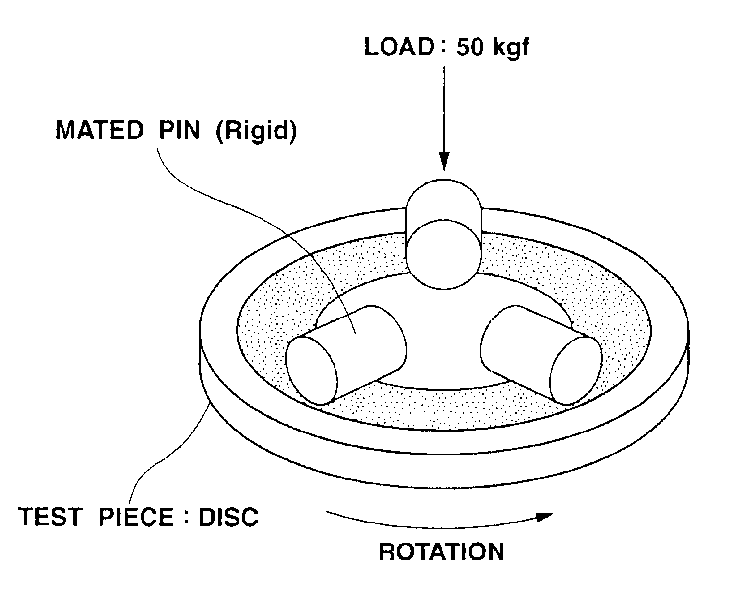
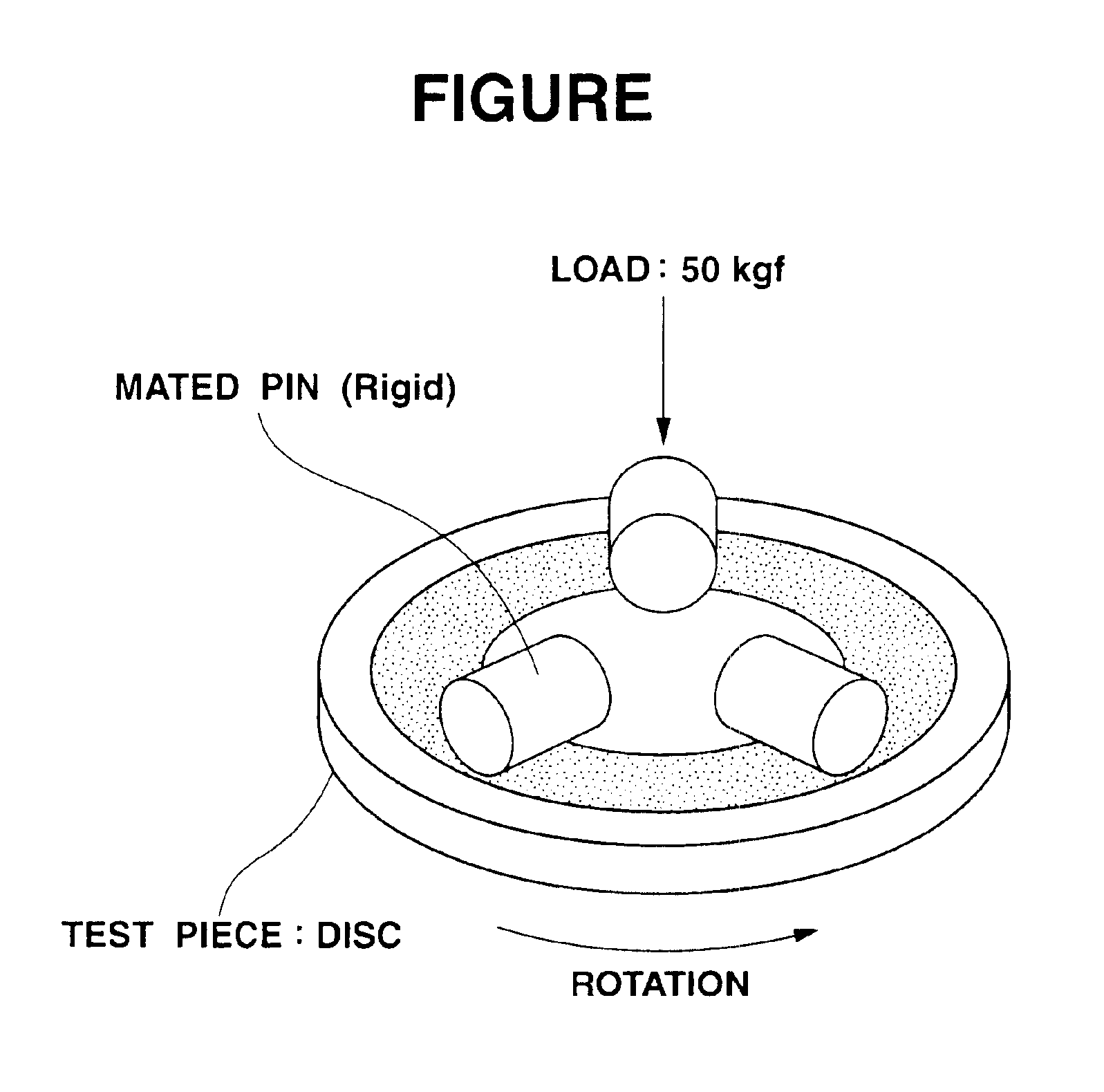
[0012]A sliding mechanism according to an exemplary embodiment of the present invention includes a first sliding member having a sliding surface, a second sliding member having a sliding surface slidable relative to the sliding surface of the first sliding member, and a lubricant applied to the sliding surfaces of the first and second sliding members.

[0013]The first sliding member has at least its sliding surface made of a diamond-like carbon (DLC) material, and generally includes a base made of e.g. an iron-based material, an aluminum-based alloy material or a resinous material and a coating of DLC material (hereinafter just referred to as a “DLC coating) applied to the base so as to define the sliding surface. The first sliding member may alternatively be formed in one piece of DLC material. Herein, the DLC material is defined as a...


PUM

PropertyMeasurementUnit
arithmetic mean roughnessaaaaaaaaaa
thicknessaaaaaaaaaa
surface roughnessaaaaaaaaaa

Abstract

A low-friction sliding mechanism includes first and second sliding members having respective sliding surfaces slidable relative to each other and a lubricant applied to the sliding surfaces of the first and second sliding members. At least the sliding surface of the first sliding member is made of a diamond-like carbon material, and at least the sliding surface of the second sliding member is made of either an aluminum-based alloy material, a magnesium-based alloy material or a diamond-like carbon material. The lubricant contains a base oil and at least one of an ashless fatty-ester friction modifier and an ashless aliphatic-amine friction modifier.

Description

BACKGROUND OF THE INVENTION[0001]The present invention relates to a sliding mechanism having excellent low-friction characteristics, particularly of the kind for use in an internal combustion engine, a drive train or a hard disk drive.[0002]Global environmental problems such as global warming and ozone layer destruction are coming to the fore. As it is said that the global warming is significantly effected by CO2 emission, the reduction of CO2 emission, notably the setting of CO2 emission standards, has become a big concern to each country.[0003]One of challenges to reduce CO2 emission is to improve vehicle fuel efficiency that depends on the performance of engine sliding members and a lubricant applied thereto. There are the following approaches to improving vehicle fuel efficiency: (1) to provide higher abrasion resistance and a lower friction coefficient for the sliding members, which are generally made of steel materials in the earlier technology, even under extreme conditions o...

Claims


Application Information

Patent Timeline
Patent Type & Authority Patents(United States)
IPC IPC(8): C10M163/00F16C33/10F16C33/12F16C33/16F16C33/66
CPCC10M163/00F16C33/04F16C33/10F16C33/109F16C33/12C10M2203/1006C10M2205/0285C10M2207/028C10M2207/289C10M2215/042C10M2215/28C10M2219/046C10M2219/068C10M2223/045C10N2210/02C10N2210/06C10N2240/04C10N2240/10C10N2240/204F16C2206/04F16C2204/20F16C2204/26C10N2010/12C10N2010/04C10N2040/04C10N2040/18C10N2040/25
Inventor KONISHI, SHOZABUROKANO, MAKOTOYASUDA, YOSHITERUMABUCHI, YUTAKAHAMADA, TAKAHIROTAKESHIMA, SHIGEKITSUSHIMA, KENJI
Owner NISSAN MOTOR CO LTD
Why Eureka
Try Eureka