High-speed vision sensor with image processing function
a high-speed vision and function technology, applied in the field of high-speed vision sensors with image processing functions, can solve the problems of limited image processing speed in modern vision systems, inability to take full advantage of robot performance, and only operating at low speeds that match this image processing speed, etc., to achieve simple circuit construction and high speed
- Summary
- Abstract
- Description
- Claims
- Application Information
AI Technical Summary
Benefits of technology
Problems solved by technology
Method used
Image
Examples
example 1
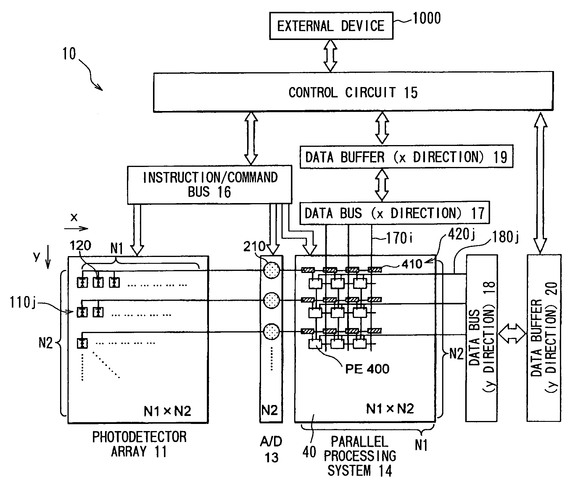
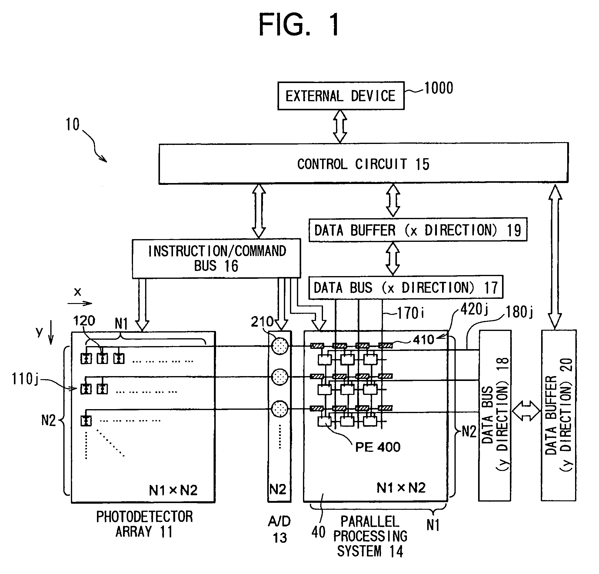
[0103]According to the present embodiment, calculation data and calculation-control data can be supplied to each processing element within a short period of time via the x-direction data bus 17 and the y-direction data bus 18 from outside. Accordingly, calculation can be attained at a high speed even when each processing element 400 performs in S110 a type of calculation that requires additional data other than image information. For example, in order to calculate the center of gravity of the input image during the image processing step (S110), the processing elements require positional information data. Accordingly, positional data is supplied from outside to the processing elements, which in turn calculate the center of gravity. Next will be described in detail the operation performed when the center of gravity is calculated during the image processing procedure (S110).
[0104]It is noted that the memory 151 in the control circuit 15 previously stores therein x-direction positional ...
example 2
[0161]The parallel processing method employed by the present system is called SIMD, and is for conducting equivalent processings at all the processing elements. It is possible to attain a more flexible processing by allowing respective pixels to perform different processings or by allowing only a certain pixel to perform a special processing. According to the present embodiment, by using the data buses 17 and 18, it is possible to allow the respective processing elements 400 to perform different processings. This is because it is possible to transfer calculation-control data to the respective processing elements 400 via the x direction data bus 17 and the y direction data bus 18.
[0162]For example, when it is desired to allow only a certain pixel to perform a special processing, the objective pixel ((x1, y1), for example) is designated by the x direction data bus 17 and the y direction data bus 18. That is, data (1) is transferred through the lines of (x1, y1) while data (0) is trans...
example 3
[0173]By using the data buses 17 and 18, it is possible to retrieve a content (calculated result) from the register matrix 401 of a certain processing element 400 after all the processing elements perform predetermined calculations.
[0174]In more concrete terms, a calculating-outputting process (S650) can be performed as shown in FIG. 14 during the image processing procedure S110 of FIG. 8.
[0175]It is noted that when the calculating-outputting process (S600) is started, image data I(x, y) at each pixel of the input image D has already been transferred in S104 (FIG. 8) from the corresponding transfer shift register 410 to the register matrix 401 of the corresponding processing element 400(x,y), and is being stored in some region in the register matrix 401.
[0176]During the calculating-outputting process (S650), first, in S660, each processing element 400 is controlled to perform a desired calculation onto image data I(x,y). As the desired calculation, various processings, such as the e...
PUM
 Abstract
Description
Claims
Application Information
 - R&D
- Intellectual Property
- Life Sciences
- Materials
- Tech Scout
- Unparalleled Data Quality
- Higher Quality Content
- 60% Fewer Hallucinations
Browse by: Latest US Patents, China's latest patents, Technical Efficacy Thesaurus, Application Domain, Technology Topic, Popular Technical Reports.
© 2025 PatSnap. All rights reserved.Legal|Privacy policy|Modern Slavery Act Transparency Statement|Sitemap|About US| Contact US: help@patsnap.com


