Optical component packaging device

a technology of optical components and packaging devices, applied in the field of packaging devices, can solve the problems mechanical failure, and the like, and achieve the effects of reducing water ingress, reducing the risk of thermally induced mechanical stresses on optical fibers, and minimizing the ratio of transversal cross-sectional area

Active Publication Date: 2005-12-13
ITF TECH
View PDF52 Cites 12 Cited by
  • Summary
  • Abstract
  • Description
  • Claims
  • Application Information

AI Technical Summary

Benefits of technology

[0039]The proposed packaging device is designed so as to allow for its sealing components to be made out of widely available thermally curable epoxy. The epoxy is preferably mixed with an ultra-low or a negative CTE filler so as to obtain the desired CTE chain and, hence, again reduce the risks of imparting thermally induced mechanical stresses on the optical fiber.
[0040]The proposed packaging device is also specifically designed so as to reduce water ingress generally associated with the use of epoxy by optimizing the configuration of the sealing component and adjacent structures. More specifically, the packaging device is designed so as to minimize the ratio of transversal cross-sectional area to the length of the sealing component in order to reduce water diffusion through the epoxy seal. Furthermore, at least a section of the optical fiber interfacing with the sealing component is preferably deprived of its protective coating so that the sealing component may contact the bare fiber in order to eliminate the risks of contaminant ingress through the fiber protective coating.
[0041]Conveniently, the proposed packaging device is provided with an aligning holder or substrate designed so as to reduce possible misalignment between the optical component, segments of optical fiber coupled thereto and the housing. Maintaining proper alignment between these components further reduces the risks of imparting mechanical stresses on the optical component and / or segments of optical fiber coupled thereto.
[0042]In accordance with an embodiment of the present invention, there is provided an optical component packaging device in combination with an optical component optically coupled to a strip of optical fiber, the strip of optical fiber defining a fiber longitudinal axis, the strip of optical fiber being made of an optical fiber material defining an optical fiber coefficient of thermal expansion, the strip of optical fiber including a fiber core surrounded by a fiber cladding coated with a protective jacket, the strip of optical fiber defining a fiber outer surface, the optical component packaging device comprising: a housing, the housing defining a housing peripheral wall encompassing a housing inner volume, the housing peripheral wall having a housing aperture extending therethrough and leading into the housing inner volume, the housing being made of a housing material defining a housing coefficient of thermal expansion; an intermediate component, the intermediate component being substantially sealingly attached to the housing so as to cover the housing aperture, the intermediate component being made of an intermediate component material defining an intermediate component coefficient of thermal expansion, the intermediate component being provided with a generally encompassing intermediate component channel extending therethrough, the intermediate component channel defining an intermediate channel inner surface and an intermediate channel longitudinal axis; the housing aperture and the intermediate component channel being configured, sized and positioned so as to allow the strip of optical fiber to extend from a position located inside the housing inner volume to a position located outside the packaging device while defining a fiber-to-channel spacing between the fiber outer surface and the intermediate channel inner surface; a sealing component in sealing contact with both the fiber outer surface and the intermediate channel inner surface, the sealing component being made of a sealing component material defining a sealing component coefficient of thermal expansion, the sealing contact of the sealing component with both the fiber outer surface and the intermediate channel inner surface being facilitated by the relationship between the sealing component, the intermediate component and the optical component coefficients of thermal expansion.
[0043]In accordance with the present invention, there is also provided an optical component packaging device for protectively enclosing an optical component optically coupled to a strip of optical fiber, the strip of optical fiber defining a fiber longitudinal axis, the strip of optical fiber being made of an optical fiber material defining an optical fiber coefficient of thermal expansion, the strip of optical fiber including a fiber core surrounded by a fiber cladding coated with a protective jacket, the strip of optical fiber defining a fiber outer surface; the optical component packaging device comprising: a housing, the housing defining a housing peripheral wall encompassing a housing inner volume, the housing peripheral wall having a housing aperture extending therethrough and leading into the housing inner volume, the housing being made of a housing material defining a housing coefficient of thermal expansion; an intermediate component the intermediate component being substantially sealingly attached to the housing so as to cover the housing aperture, the intermediate component being made of an intermediate component material defining an intermediate component coefficient of thermal expansion, the intermediate component being provided with a generally encompassing intermediate component channel extending therethrough, the intermediate component channel defining an intermediate channel inner surface and an intermediate channel longitudinal axis; the housing aperture and the intermediate component channel being in communication with each other so as to allow the strip of optical fiber to extend from a position located inside the housing inner volume to a position located outside the packaging device; a sealing component in sealing contact with the intermediate channel inner surface, the sealing component being made of a sealing component material defining a sealing component coefficient of thermal expansion; the intermediate component coefficient of thermal expansion being greater than the sealing component coefficient of thermal expansion; whereby, the sealing component is in sealing contact with both the fiber outer surface and the intermediate channel inner surface, the sealing contact of the sealing component with both the fiber outer surface and the intermediate channel inner surface being facilitated by the relationship between the sealing component, the intermediate component and the optical component coefficients of thermal expansion.
[0044]Conveniently, the intermediate component channel defines a sealing section, the sealing section defining a sealing section opening area and a sealing section length, the ratio of the sealing section opening area to the sealing section length being minimized so as to reduce water ingress through the sealing component in the sealing section.

Problems solved by technology

Some optical components are particularly vulnerable to mechanical stresses.
In certain instances, this vulnerability is directly linked to the inherent structure of the optical component.
Indeed, some optical components being made of modified glass fibers, they are characterized by an inherent brittleness that can lead to mechanical failure.
The adjacent sections of optical fibers coupled to the optical components are also often particularly vulnerable to mechanical stress, especially if they have been locally stripped of their protective coating.
Aside from potentially causing breakage of the optical component and / or the adjacent sections of optical fiber attached thereto, bending or other mechanical stresses imposed thereon may potentially cause degradation of optical performances by inducing changes in optical signal strength and content.
Moisture in particular may prove to be detrimental to some optical components for several reasons.
However, unfortunately, overtones of this wavelength produce three loss peaks within the 700 to 1600 nm band, and these can interfere with signal transmission.
Moisture also tends to exaggerate surface flaws and, hence, lower tensile strength of the optical component and strips of optical fiber coupled thereto.
Furthermore, when exposed to gaseous hydrogen, some optical components show an increase in optical loss that can be either temporary or permanent, depending on whether the hydrogen simply diffuses into the component and then leaves, or remains long enough to react chemically with the fiber.
One of the main drawbacks associated with the hereinabove mentioned type of prior art optical component packages is that the relatively short and wide epoxy-based sealing plugs typically do not provide an efficient barrier against moisture ingress into the tube ends.
Indeed, it is well known that the physical characteristics of cured epoxies are such that they have a tendency to absorb and allow ingress of moisture.
Most prior art packaging devices using silicone sealing plugs however are not designed so as to reduce the A / L ratio and, hence, offer relatively poor protection against humidity ingress.
Another main drawback associated with the hereinabove disclosed type of prior art optical component packages is that the optical component and at least a section of the optical fiber attached thereto are often susceptible of being subjected to mechanical stresses if the optical component package is subjected to temperature variations.
Temperature variations may prove to be particularly deleterious in situations wherein the optical component and / or the strips of optical fiber attached thereto are solidarly anchored at spaced apart locations to a rigid sealing component and to a fixed mounting fixture within the housing.
In this respect, maintaining the stability and relative position of optical fibers, components and devices, through the correct choice of materials, is particularly critical in that even minor relative movements between such elements may result in large variations or degradation in optical characteristics.
The thermally induced mechanical stresses to which some optical components are subjected to are typically imputable to the mismatch between the coefficients of thermal expansion of the various components involved.
Indeed, as is well known, when two dissimilar materials are joined together and subjected to thermal cycling, the difference in their coefficients of thermal expansion can induce relatively large structural stresses.
Furthermore, depending on the exact geometry and material distribution, the induced structural stress fields, although often transient, may be quite complex.
Some thermally induced stress concentration points may potentially damage relatively fragile microstructures.
However, the sealing plugs and the fiber to which they are bound typically remain made out of generally dissimilar classes of material, namely a polymeric material such as epoxy and a glass-based material such as silica leading to thermally induced mechanical stresses.
These thermally induced mechanical stresses are susceptible of exceeding the adhesion strength of the seal, hence potentially resulting in delamination during thermal cycling.
However, the use of silicone is associated with some important drawbacks such as a relatively poor sealing efficiency.
Indeed, sealing plugs made out of silicone may not form strong chemical bonds with the outer surface of the optical fiber.
Furthermore, silicone releases cyclosiloxane, a contaminant known to induce drift or wavelength shift in the optical components.
Although solder seals are generally considered as being relatively efficient in preventing contaminant ingress, they nevertheless suffer from numerous drawbacks.
The surface metalization process is both tedious and time consuming.
This reduction in the tensile strength of the surface metallized portion may result from factors inherent to the process including the creation of micro-cracks during the removal of the fiber coating and stresses generated during both metalization and soldering steps.
Some of the glass-seal structures suffer from the same drawbacks as the hereinabove disclosed other types of seals.
In particular, some of the prior art glass-seal structures suffer from drawbacks associated with mismatches between the coefficient of thermal expansion of the sealing plug and of the housing protecting the fiber.
Although the glass-seal structure disclosed in U.S. Pat. No. 5,664,040 at least partially solves some of the hereinabove mentioned drawbacks associated with other prior art sealing structures, it nevertheless inherently suffers from other drawbacks prohibiting its use in certain settings.
The document mentions the use of a sealing glass preferably having a softening temperature in the range of about 700° C. to 900° C. This inherently relatively high softening or temperature may prove to be unacceptable in certain settings, for example when heat sensitive optical components are packaged especially if thermally sensitive adhesives are also used in the package.
Furthermore, glass-based sealing materials have also been associated with the release of contaminants during reflow.
These contaminants may potentially induce drift or wavelength shift in the optical components.

Method used


Image

  • Optical component packaging device
  • Optical component packaging device
  • Optical component packaging device

Examples


Embodiment Construction

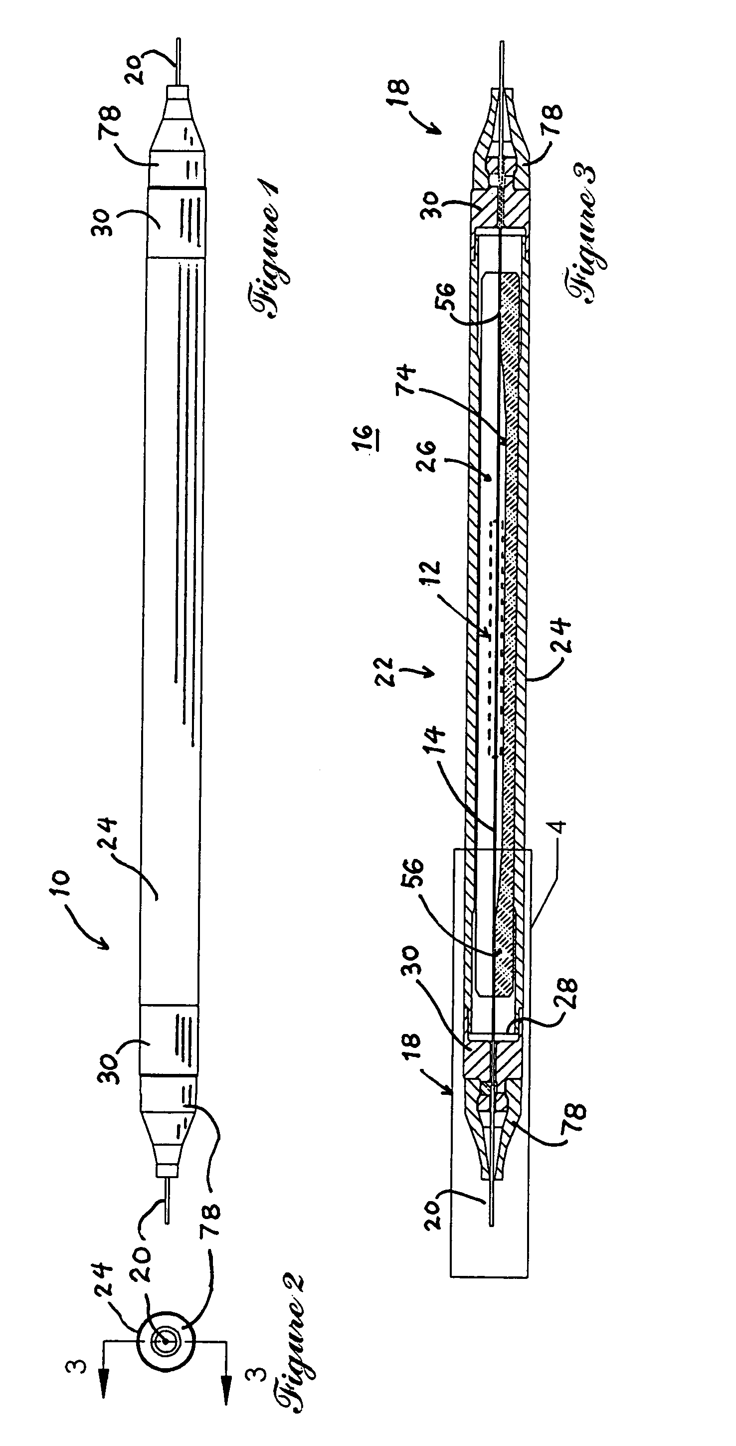
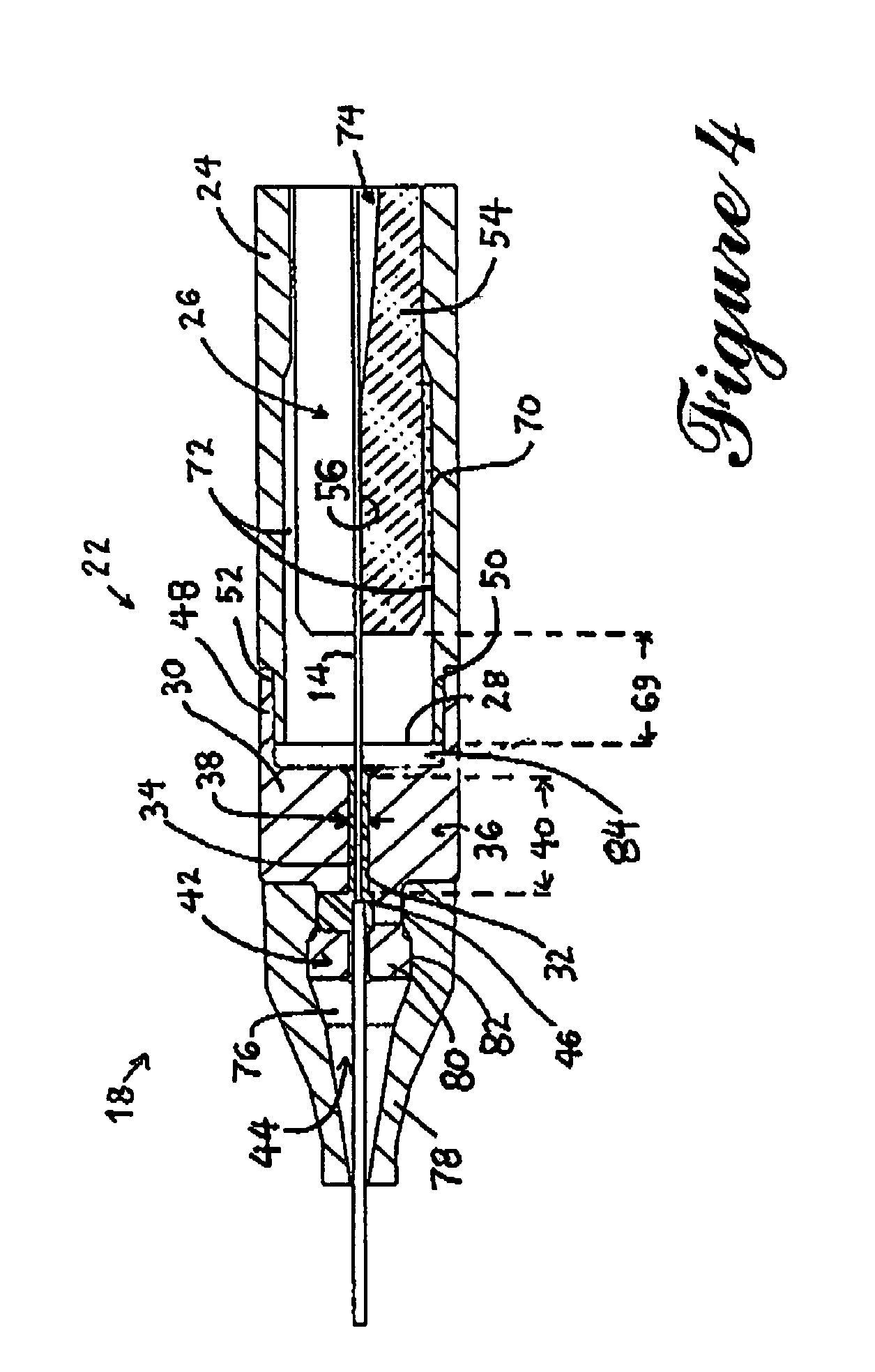
[0055]Referring to FIG. 3, there is shown, in a longitudinal cross-sectional view, an optical component packaging device (10) in accordance with an embodiment of the present invention. The optical component packaging device hereinafter referred to as the packaging device (10) is intended to protectively enclose an optical component schematically illustrated in FIG. 3 and designated by the reference numeral (12).

[0056]The optical component (12) can be of any suitable type such as a coupler, a multiplexer / demultiplexer, a connector, a filter, a switch or any other optical component (12) requiring protection from the external environment. The optical component (12) is typically optically coupled to at least one so-called pigtail or strip of optical fiber (14) allowing the optical component (12) to be optically linked to the external environment (16).

[0057]In the embodiment illustrated in FIG. 3, the optical component (12) is shown coupled to a pair of strips of optical fiber (14) exten...


PUM


Abstract

A packaging device for protectively enclosing an optical component in a substantially clean and anhydrous environment without imparting undue mechanical stresses on the optical component and adjacent segments of optical fiber coupled thereto. An intermediate component is used in combination with a sealing material for sealing the fiber aperture of a protective housing while allowing an optical fiber to extend therethrough. The protective housing is made out of a material having a coefficient of thermal expansion that closely matches that of the optical fiber. A chain of material CTE that includes the CTE of the intermediate component is used in order to circumvent the need for a sealing material having a high melting temperature. The packaging device is also designed so as to reduce water ingress by optimizing the configuration of the sealing component and adjacent structures.

Description

FIELD OF THE INVENTION[0001]The present invention relates to the general field of packaging devices and is particularly concerned with a packaging device for protectively enclosing optical components that are optically coupled to strips of optical fiber.BACKGROUND OF THE INVENTION[0002]The use of optical fibers for various telecommunication systems and other applications has become increasingly prevalent. It has led to the creation of a whole burgeoning industry over the past few years. In the foreseeable future the field of fiber optics is expected to experience a quantum leap in both stature and product diversification.[0003]As is well known in the art, optical fibers are typically hair thin structures, capable of transmitting light signals at relatively high rates and with relatively low signal loss. They are believed to be ideally suited to the high requirements of digital transmission and, hence, are well matched to the evolving worldwide data transmission network.[0004]In orde...

Claims


Application Information

Patent Timeline
Patent Type & Authority Patents(United States)
IPC IPC(8): G02B6/42
CPCG02B6/4248
Inventor SEGUIN, FRAN.CEDILLA.OISMARTINEAU, PIERREBRULOTTE, DENIS-ALEXANDRECIGANA, PATRICKOCTEAU, PASCALDAXHELET, XAVIERALLARD, SEBASTIEN
Owner ITF TECH
Why Eureka
Try Eureka